I started thinking about ball juggling machines in the year 2015. I wrote about my first few attempts at creating them in this blog post from the year 2017. In 2018 I wrote another post about my then newest build. We’re now in the year 2020. And finally, the quest to get a machine to juggle a ping pong ball reliably has come to an end (as this current build is able to keep the ball bouncing for hours.)
Components
This machine requires the following things to work:
- 1x Teensy 4.0 Microcontroller running this code
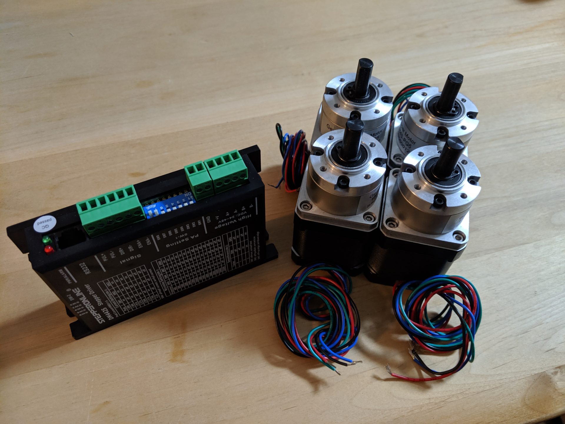
- 4x StepperOnline DM442S stepper motor drivers
- 4x Nema 17 Stepper Motors with 5:1 planetary gearbox
- 1x 48V 8A power supply
- 1x e-con Systems See3CAM_CU135 camera
- 1x Windows Computer with OpenCV installed on it
- All the parts defined in this Fusion360 project
- This custom Windows Application (made with Unity)
Why A Teensy 4.0?
Because 600 MHz. That’s the clock speed of the Teensy 4.0. Compare that to the 16 MHz you get with most Arduino boards. But why so much emphasis on clock speed anyway? Because we need to generate pulses with a frequency of up to 250 kHz for each of the 4 stepper motors. And since we want the stepper motors to start and stop smoothly, the spacing between the pulses needs to increase/decrease in a sinusoidal pattern. And yes, it doesn’t need to be sinusoidal – you could also go for a sigmoid – but the point is if you want very fast, smooth movements linearly increasing speed-curves probably won’t cut it. And because this is quite a lot of calculations to do on a 16 Mhz microcontroller I went for the Teensy 4.0.
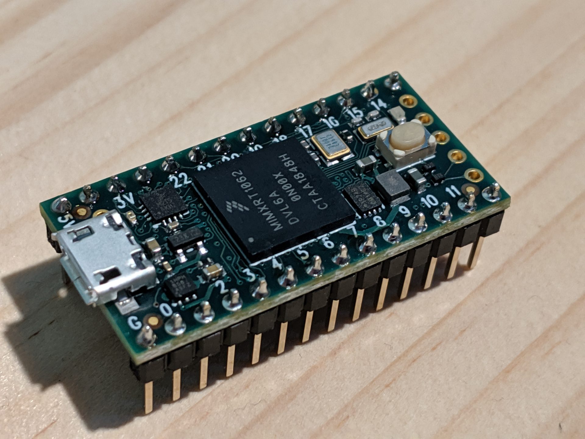
By the way, this microcontroller also comes with a FPU (Floating Point Unit) which both supports 64bit doubles and 32bit floats. As if the crazy 600 MHz clock speed in and itself wasn’t enough, now we also get an FPU!
Do we really need 600 Mhz?
But maybe you’re still not convinced. “Why do we need to generate 250 kHz pulse signals? The motors aren’t really rotating that fast are they? Won’t 10 kHz do it?” Good question. Here’s what I found out while trying to get my steppers to move as fast as possible:
- the more microsteps the better
- the higher the voltage the better
So more microsteps is better. I set the microstep setting on my drivers to 25600 steps/rev. That’s a lot of pulses for 1 single revolution. And remember that we’re using stepper motors with a 5:1 gearbox attached. So it’s really 128’000 steps per revolution. We’re getting pretty high up in the numbers already and maybe you can see now why 250 kHz isn’t that unreasonable at all.
Here’s an actual image of the first 9 milliseconds of a 150 milliseconds long pulse signal.
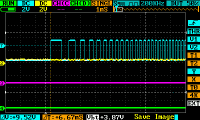
You can clearly see how the pulses are getting narrower towards the right side. The frequency is increasing smoothly. Starting slow but picking up speed as the signal progresses. Keep in mind that we’re only able to see the first 9 milliseconds of this signal. The frequency will go way up and then start to decrease again.
What exactly is the microcontroller doing?
The Teensy 4.0’s job in this project is simple.
- Listen for movement commands on the serial bus
- Generate pulses for the stepper motors
The data we’re listening for on the serial bus looks basically like this: 0.11941:0.11941:0.11941:0.11941:0.15000
There are 5 values all separated by colons. The first 4 values are absolute motor positions (in radians) and the last one is the move time. So with this instruction, we are telling the machine to move all it’s motors to the absolute position 0.11941 in 0.15000 seconds.
We’re also able to string multiple movement commands together. The machine will work through the movement commands one at the time in the order the commands came in.
What’s the desktop Application doing?
I told you that I’ve built an Application with Unity for this machine. So why did I do that? What about all that talk about that crazy fast 600 Mhz microcontroller?
The reason I ended up writing this application is that I wanted to do 120 FPS real-time image processing of 640×480 image data. So here’s what the computer application ended up doing:
- Setting up the camera (120 FPS 640×480 data stream, gain, exposure, contrast, ISO, saturation) via OpenCV
- Execute OpenCVs Hough Transform circle recognition algorithm
- Get 3D position of ping pong ball using the results of above-mentioned circle recognition algorithm
- Calculate ball velocity
- Use ball position and velocity in PID control code to calculate correction-tilt of plate
- Execute Inverse Kinematic code to figure out how much each motor needs to rotate in order to get the plate to a certain height with a specific tilt.
- Send result of IK calculation to the microcontroller via serial interface
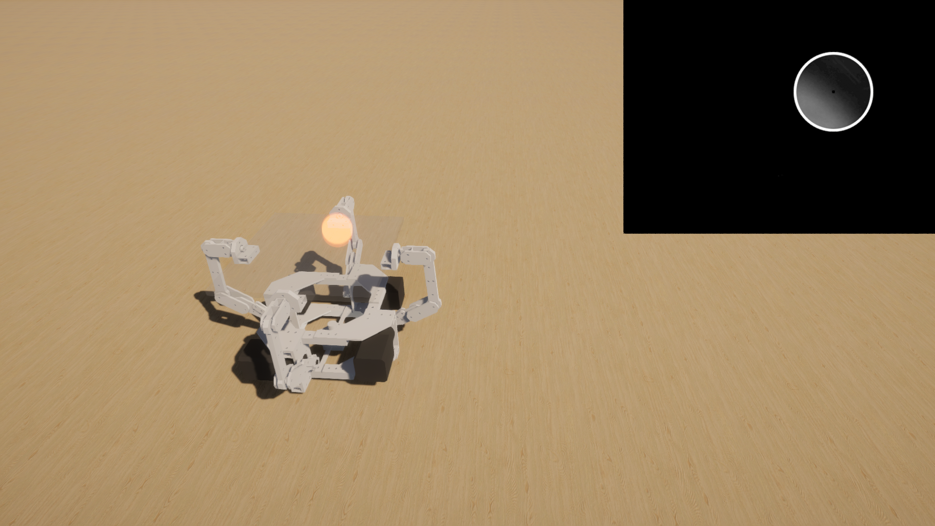
- Render machine position and movements
- Also render image processing data
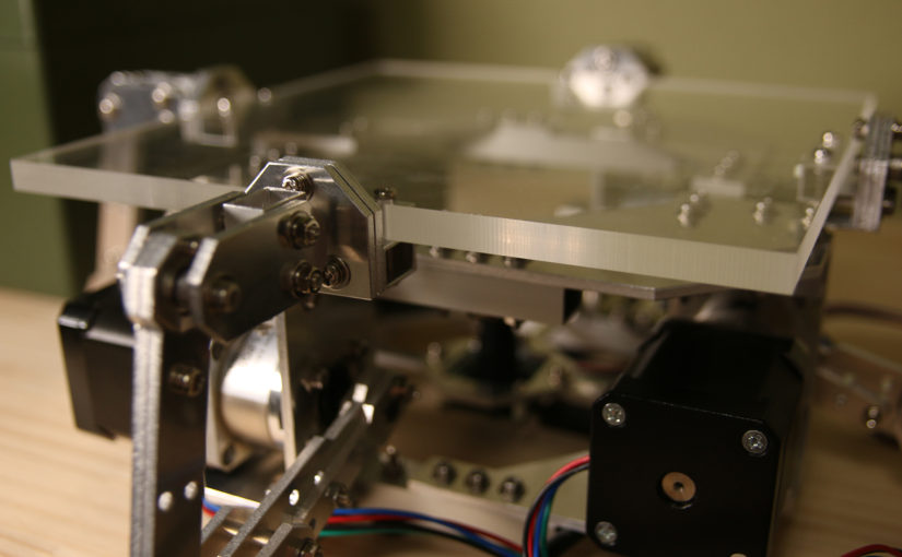
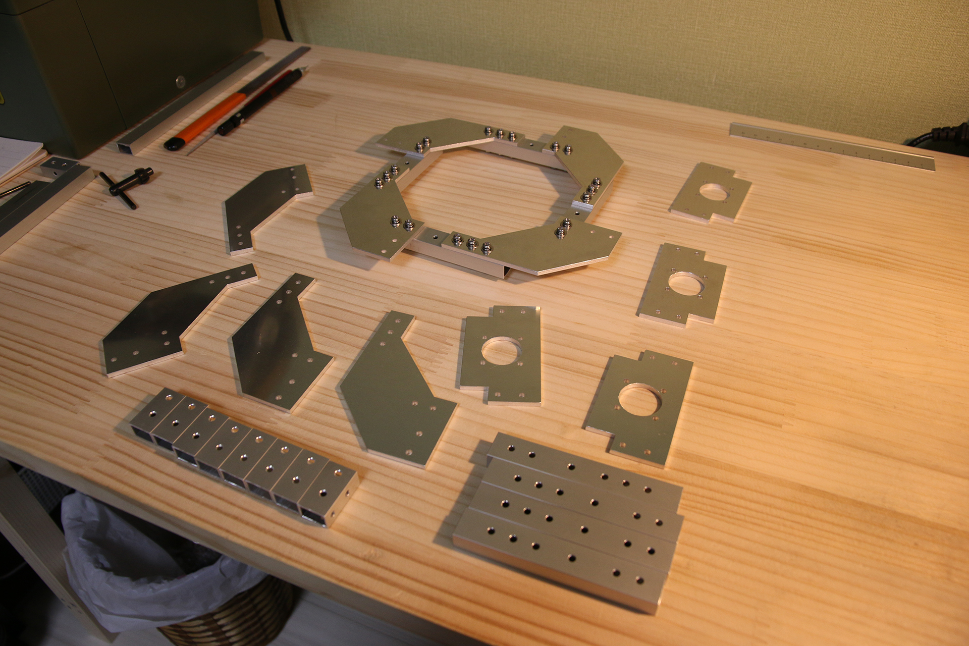
How did you make all those aluminium parts?
This machine is made of 150+ aluminium parts. And producing all these parts took A LOT of patience.
I basically ran my Benbox CNC 1310 (almost) nonstop for multiple weeks. “Multiple weeks? You must be kidding.” Well, I’m not. The total machining time for all the parts was about 160 hours.
“Why is your CNC mill so slow?” you might wonder. It’s because the spindle isn’t quite as powerful as I’d like it to be. We’re looking at an 80W spindle here. Updating the spindle is one of the things I’d like to do in the near future.
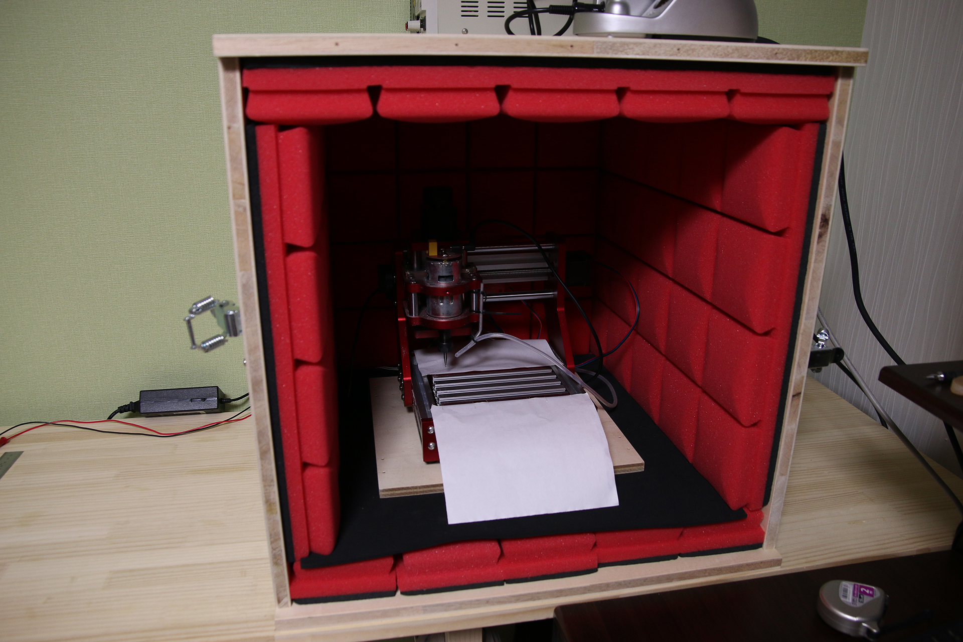
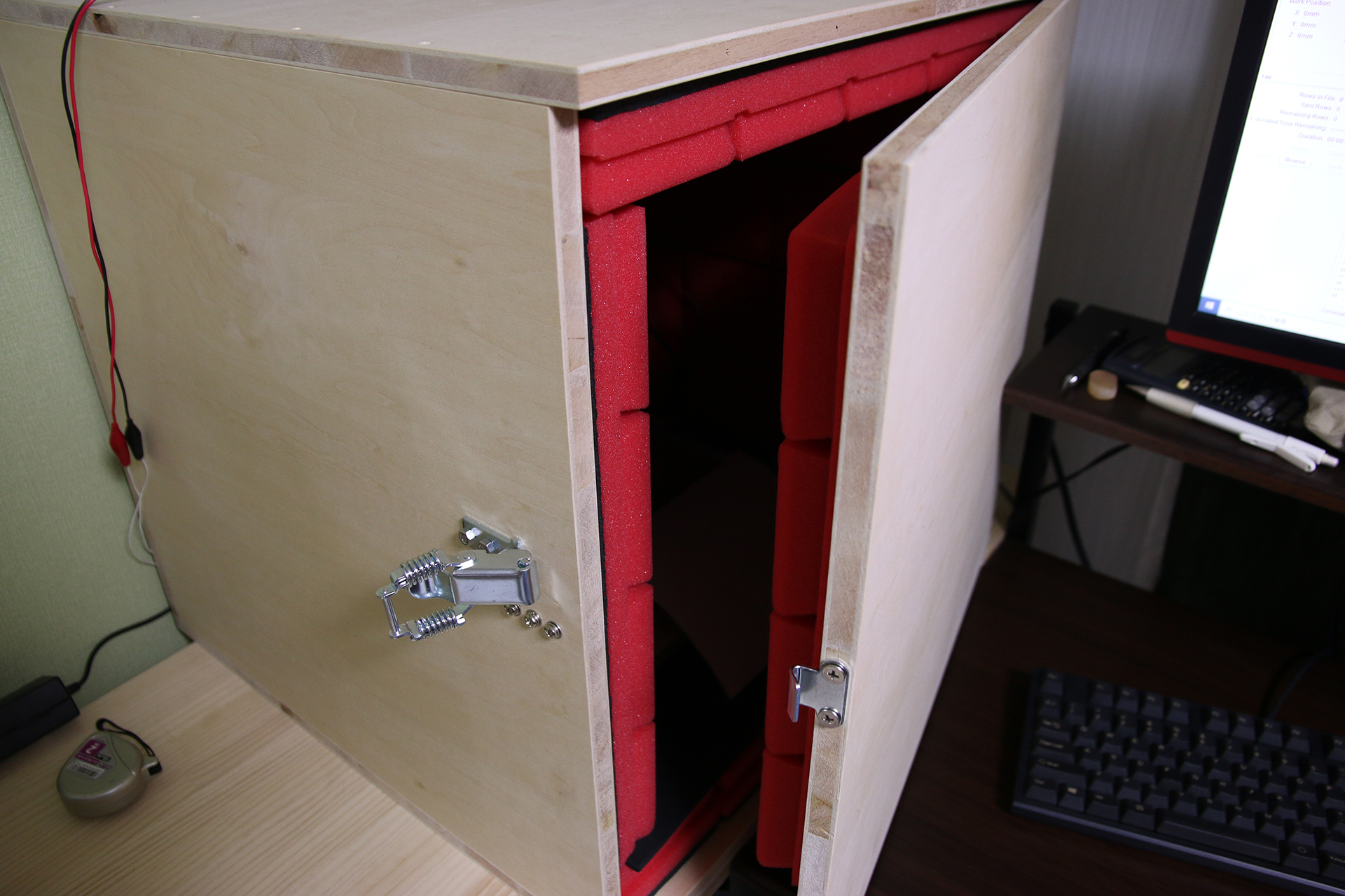
I made a sound-absorbing box for the CNC mill in order to preserve my sanity.
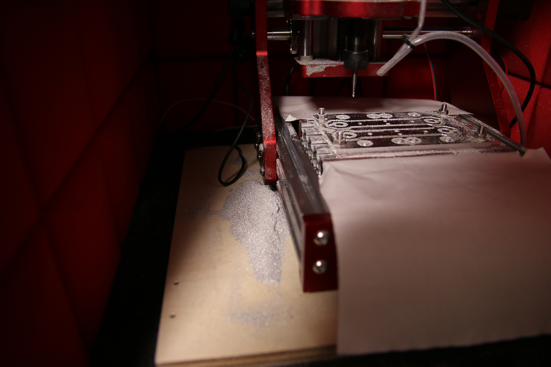
I used a 1.5mm endmill on 6061 Aluminium with a thickness of 3mm. As you can see in the image above, I fixed my workpiece with 4 screws to ensure that it is both held in place securely and the surface is as plain as possible.
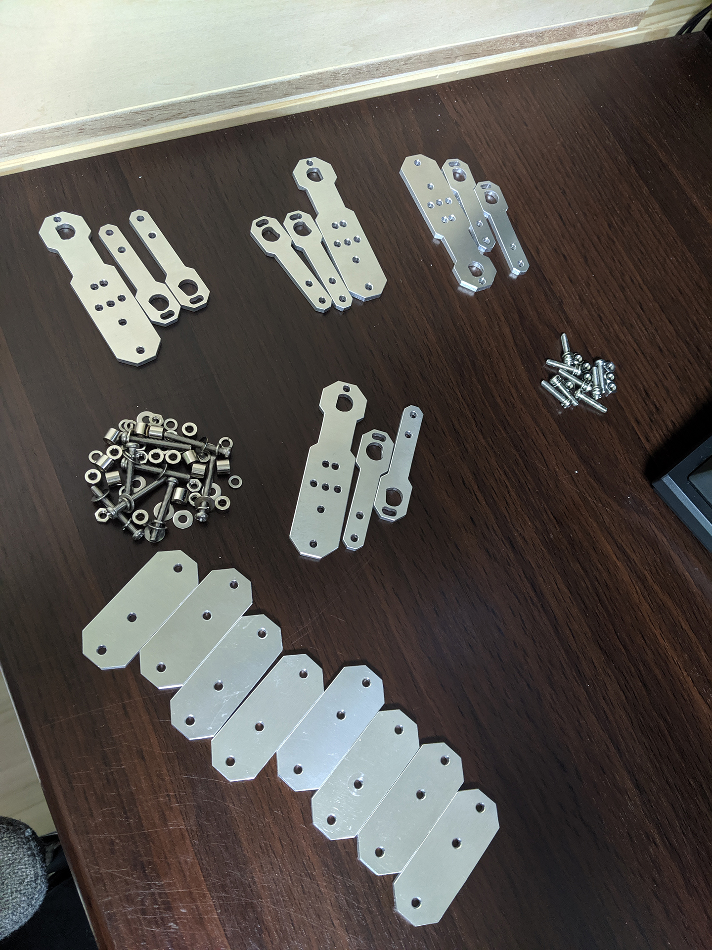
Some pics I took while working on the machine
What follows are some pictures I took while working on this project.
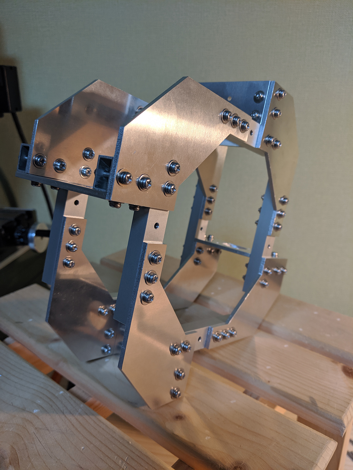
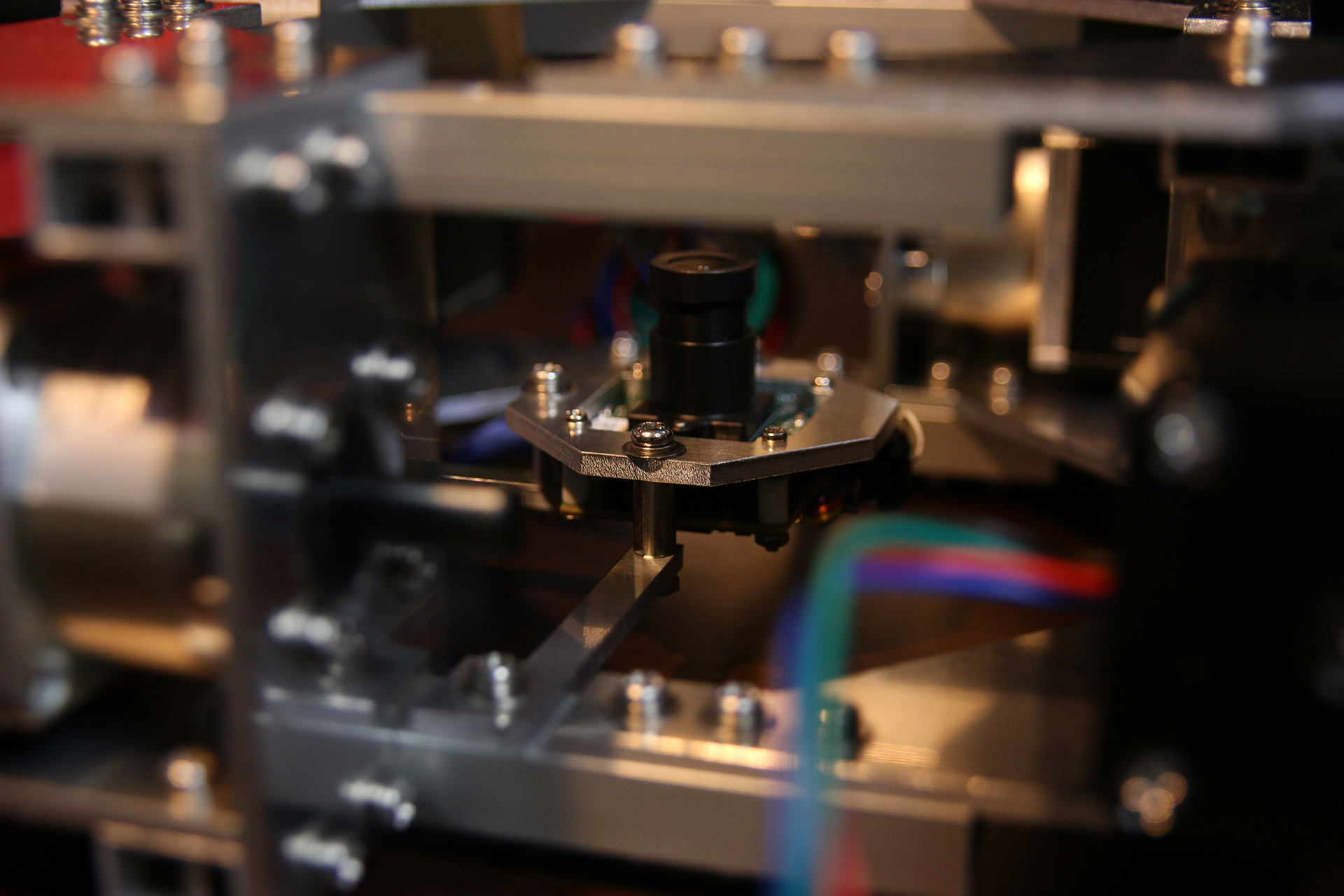
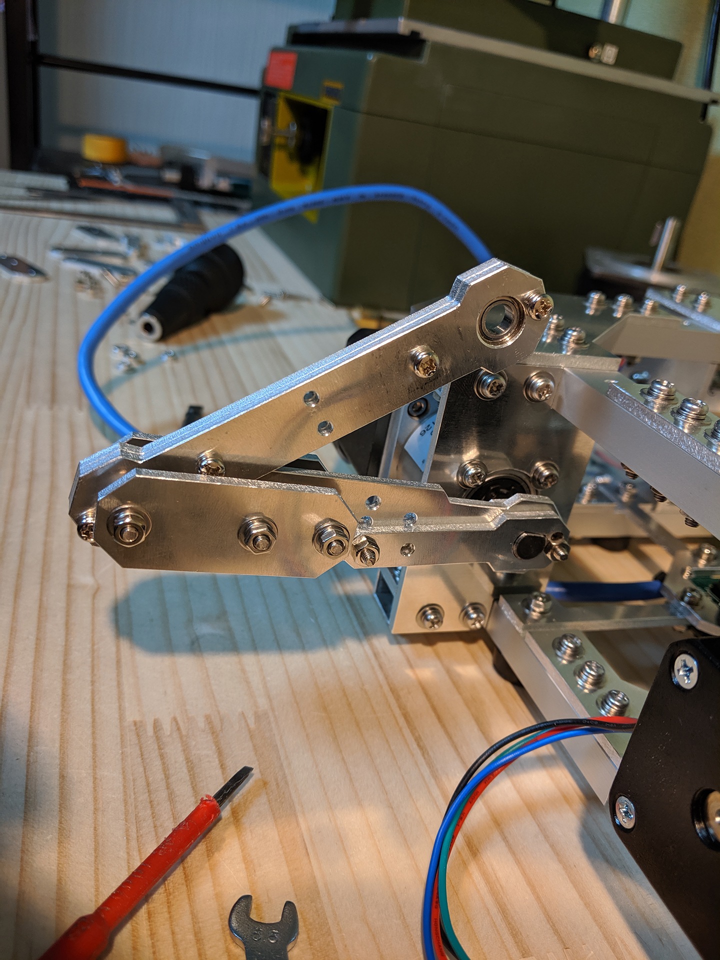
One thing worth mentioning is that I used ball bearings for all the joints. If you look closely at some of the pics above you should be able to see them.
Awesome work brother. love that level of effort, dedication, and work
Really Cool!
Question: I’ve had difficulty do vision based control projects in opencv before and the thing that really killed us was the latency in the image stream. There appeared to be about a couple frame buffer somewhere in the pipeline. Did you find a way to combat this, or it wasn’t a problem, or is that camera particularly good?
http://www.philipzucker.com/cartpole-camera-system-opencv-ps-eye-ir/
I am running the camera at 120 FPS. Maybe this why I didn’t run into problems with the buffered frames. So, to answer your question more directly; No, I didn’t notice a problematic delay in the image stream from the camera.
brother can we use the neema 23 without any palentary gear instead of neema 17 with palentary gear
Where/how did you get the camera? e-con Systems shows “volume purchase” and lists a contact number and I’ve not seen anyone else selling that camera.
The people from e-con Systems reached out to me and asked me if I wanted to try one of their cameras and maybe use it in my next project. That’s how I got one.
Hi Doug,
Sample 13MP 4K USB camera purchase from e-con’s webstore is now available . https://www.e-consystems.com/webstore-inr.asp#CU135USB
I just want to say that this is amazing work, thanks for sharing.
What sound dampening panels did you use in your CNC box?
Jay, google is your friend. FYI, switch to image view and look for the same product. https://www.ebay.co.uk/itm/6-Pcs-Acoustic-Foam-Sound-Proofing-Isolation-Panels-for-Home-Studio-White-/303021196512
ebay US – https://www.ebay.com/itm/6-Pcs-Acoustic-Foam-Sound-Proofing-Isolation-Panels-for-Home-Studio-Red/233207639611
aliexpress – https://www.aliexpress.com/item/33018501278.html
Hello, dear Tobias!
I’m one of your followers on youtube and for 2 years I’m watching you making this interesting robotic projects.
For now I’m working in small company, we perform some research on medical simulations systems, surgical simulations, etc. Now we are in great need of a new haptic system, for our own needs. And you have good approach and almost done some work in delta mechanisms – so maybe we can talk about some collaborative research or just a well payed consulting or developing of a haptic systems, compliant to our needs ??
you can write me at dr-mareev (at) mail.ru
This is great.
I am wondering if there is an application in the sex toy space for this tech. Specifically, a machine that penetrates and can ‘see’ its target even if the target moves. This would be head-over-heels better than anything that currently exists.
This is very cool….i would know how are you serially transmitting data from PC to microcontroller because i was unable to transmit integer values from pc to microcontroller though it was transmitting only char. And at which rate you are transmitting..
I am transmitting at 115200 baud. And, just like you mentioned, the data is transmitted as chars. There is a nice C function which converts a char array (c-string) into a float. Here’s the particular piece of code where I am using it:
https://github.com/T-Kuhn/HighPrecisionStepperJuggler/blob/9ab3d8b2c627158048f5ef7ec057e10ebd47787b/Arduino/HighPrecisionStepperJuggler/HighPrecisionStepperJuggler.ino#L98
Really nice work! Thank for the sharing and design~
Very Impressive. Amazed at the dedication and attention to detail. Thanks for sharing
Excellent work! well done.
Hi,
Do you have a wiring diagram you could share?
I am having trouble understanding how the Teensy connects to the drivers while I read your code.
Thanks so much for sharing your project with us.
John
There’s no wiring diagram. the drivers have a step and dir pin. The drivers controlling voltage is 5V. I used NPN transistors to interface with the drivers because the Teensy’s output pins only provide 3.3V.
Hope this explanation helps.
Hi T-Kuhn,
Thank you for the explanation; that makes sense 🙂
Would you see any problems in using a level shifter instead of the transistors?
Thanks for your time.
John
should work fine with level shifters. You might want to check the max switching frequency of your level shifter. It needs to react fast (in the 250 kHz range.)
Can you kindly send the circuit diagram of the project??
What is the 3d-simulation program?
It’s Unity!
Hi,
I’m impressed with your project and all the dedication that you have put in to it. Thanks for sharing.
I am wondering if you can provide more details about the components (if possible links) for the power supply, stepper motors, and drivers so that anyone like me can replicate it.
I am very interested in replicating your project and share the results with others.
Thanks
I ordered all the steppers and stepper drivers at StepperOnline.
StepperMotors: 17HS19-1684S-PG5
Drivers: DM442S
Power Unit (from amzon): 48V 8A
can i make this project for my youtube channel, I agree to give you proper credit,
Sure
Hi!
This project looks great, I’m working on a similar thing looking to balance a ball instead of bounce it.
I was wondering if you had any extra info on your PID controller & how you decided on the parameters?
Did you model the system and design the controller in simulation?
Thanks,
Alex
PID is a simple kind controlling algorithm. There are only a few parameters you need to get right. So – even though there might be interesting insights to be had when creating a model and simulating it – you will be just fine without going through all that. Just program your PID and start with some fairly small values. In fact, You might want to set all paremeters besied the P one to 0 for the start. Then get the system to balance the ball with P only (it will start to oscillate, but that’s okay.) Once it looks like your system’s on the right track, crank up your D-Parameter to get rid of the oscillations. The D part will correct in the opposite direction of your ball’s velocity. That’ll keep it from gaining too much speed.
Hello, I am a person who likes programming and mechanical engineering. I’m really interested in studying this project. I’d like to purchase parts for the WeProject, but the DM442S motor driver is out of stock. Is there a replacement?
I went for the DM442S because they can handle up to 200 kHz on the step input. You also want to buy a driver that supports up to at least 40V and delivers around 3A RMS. Those are the important speccs you need to look out for.
Hello, I thank you for your quick reply. So I’m looking for a replacement motor driver. Among them, I’m looking for a product called DM542S on the https://www.omc-stepperonline.com/digital-stepper-driver/dm542s.html site, so is it possible to replace it? I want to use the same code you posted, should I change the code?
Excellent.. Big thanks for sharing
Hi T-Kuhn,
Would love to get my kids into functional engineering like this instead of buying lego mindstorms etc. Any recommendations on where to start? Is there a popular forum with small projects to get started?
Loved the video and machine, great work!
Hi Brandon,
There are some hurdles to overcome when it comes to projects like this. Designing a simple machine in Fusion360 is easy enough, but after that you need to set up your CNC mill and work piece.
The work piece needs to be held in place firmly and parallel to the worktable. To achieve this for an aluminium work piece with a thickness of about 3mm I found that drilling holes on all 4 corners and screwing it down to the worktable worked best for me.
After this, you’ll need to figure out good parameters for your specific CNC mill. How fast do you want it to move (feed rate)? How much material should be removed at each iteration (this is presuming you’ll use a table top CNC mill; they usually aren’t able to mill more than a fraction of a mm at a time, so you need to iterate the same path over and over again while stepping down a bit each time.)
What I want to get at here is that just getting a CNC mill running is a considerably big project with a lot of trial and error involved. If you chose to go down this route, make sure you’re kids understand that it takes time to get it all set up. On the bright side: Once it’s all running you’ll be able to produce custom aluminium parts!
As for project ideas. Here’s a good site: https://hackaday.io/discover
Your little machine is awesome 🙂 nice work! Just wondering how you went about creating the inverse kinematics? From the outside this seems like the most challenging part of the project! Also, I assume the routine used to start the ball bouncing was hard coded?
Hi Glen,
About a year ago I started thinking about a 4 armed machine design like this and started working on the forward kinematics for a single arm. As you probably know, getting the forward kinematics isn’t that hard. So after I convinced myself that the forward kinematics equations I ended up with were sound I worked out the inverse kinematics ones (using wolframalpha.com for some guidance along the way.) After making sure that the IK equations worked and everything moved accordingly (I implemented the IK equations in Unity and moved my model data around to check this) I moved on and added the plate to the arms.
My input values for the IK as a whole are height and plate tilt (x-tilt, y-tilt.) For a specific height and tilt combination the resulting arm tip positions can be obtained with basic trigonometry. So now that we know where each of the 4 arms has to be, it’s only a matter of applying the 1-arm IK to all of them to figure out how much each of the motors has to rotate. That’s basically it. Implementing the IK equations in Unity and being able to check everything in a 3D rendering environment (without needing to worry about motors wreaking havoc) helped a lot.
You are – in a way – correct about the start-up routine used to get the ball bouncing; It is hard coded. Though there is some PID control in it to keep the ball close to the center, so there is a dynamic part to it too (the tilt, to be specific. The height movements – and the number of up-down movements for that matter – are hard coded and won’t change no matter what.)
Hi, great job. I was just wondering, isn’t a plane’s position determined by just three points and not 4? I would think that just three of the arm tips would fully define the position of the plate. Also, wouldn’t simultaneous X-tilt and Y-tilt result in a lateral movement on the arms in this direction? Am I wrong to think that? Image to make this clearer -> https://imgur.com/a/tVmBPIR
Hope you would reply. Thank you.
Hi Stephen,
You are right; the exact same movements could be achieved with a 3 arm design.
Not only are the same movements possible, but the 3 arm design handles simultaneous x- and y-tilt better. As you noticed, with this 4 arm design simultaneous tilts will result in a shifting plate.
http://www.electrondust.com/wp-content/uploads/2020/06/10_10-tilt.png
Trying to get 10 degrees x- and y-tilt simultaneously on the model shows that something’s not quite right.
With the actual machine, going up to 5 degrees simultaneously works because there is enough play in the joints.
That’s a really cool insight on how you went about making this machine. Thank you!
Phenomenal stuff! Looking forward to seeing your future projects 🙂
Hi T-Kuhn,
This is incredible stuff! I have a question for you. In the article you have mentioned the following with a sample movement comment to the Teensy 4.0.
“So with this instruction, we are telling the machine to move all it’s motors to the absolute position 0.11941 in 0.15000 seconds.”
Assuming this is a realistic movement instruction that takes 150 ms, is it that movement comments do not take place nearly as fast as the camera is gathering ball position and velocity information? If so, at what frequency are movement instructions being sent to the microcontroller? Thanks!
Oh yes, movement commands are quite sparse in general. Here’s how it works for a single bounce:
1. Camera watches ball and gathers as much data as possible (mainly position and velocity) in order to compute the tilt the plate will need to aim for while moving up.
2. As soon as the ball is falling back down and has reached a certain threshold distance the machine will send a single(!) move command to move the plate up while simultaneously tilting it.
3. This move command is followed by another move command to get the plate down again.
This is basically it. I optimized some parts of it a bit in the meantime. The machine now tilts the plate already while going down using a prediction where the ball will go down. But the number of move commands is the same.
I could however send more move commands. And that’s exactly what’s happening when the machine balances the ball (like in the video I attached to this blog post.) Since the move commands are really short it looks like the machine is moving fluidly even though it actually is just processing really small move commands in fast succession.
Hello author, I would like to ask if I can use Arduino instead of teensy ?
Great job!
I have a question;
Arms are 10 cm or 20 cm ? I open the fusion 360 project file and it is 10 cm but it looks bigger in the real life. Am I wrong ?
They really are 10 cm. All the measures in fusion 360 should be correct.
Thanks, I have another question. Without the reductor (gearbox), is it possible to lift the plexiglass ? Can a stepper lift the class without gear ?
For the same build, I think you might get it to move the same way if you’d use nema23 motors instead of the nema17 motors I used. The problem boils down to “how fast can we start/stop the stepper motors without having them skip steps.” No gear means the motor needs to handle the full load. When applying speed curves with a high acceleration this might be problematic. That’s why I think it might be too much for a nema17 without gear.
How can you calculate velocity of the ball in 3d? I can find x,y speed vectors and radius of the ball with Opencv. But I can’t find the z-axis speed of the ball. And to predict where will ball fall on the plate I need that info. Thanks for the answers.
You just calculate it from your position data. A simple approach would be to look at the x-position and compare it to the x-position 1 second later. if the ball moved 10mm in the x-direction the ball’s speed will be 10mm/sec.
You might think “I don’t want to wait for a full second, I’ll calculate the speed every frame with the current position and the position on the last frame.” But you need to be careful here. say you are gathering image data at 100 FPS. That’s 1 image every 10ms. So you will be comparing the ball position of two frames which were taken 10ms apart. In an ideal world, there wouldn’t be anything to worry about. But the world isn’t ideal. There will be a bit of noise in your position data. This noise might be only a few millimeters, but if you consider that the ball might not even move a full milimeter in 10ms this will become a problem as the speed you are calculating will now consist of the real distance the ball moved (say 0.5mm) and the noise in the image data (say 1mm.) So you’ll get 1.5mm/10ms which is 150mm/sec instead of the correct speed the ball is actually moving.
Hi, I am trying to make a similar machine (except it does only ball balancing). I find that the PID control motion is very jerky as it responds to the feedback from the camera, which sometimes is a bit noisy. How do you achieve such smooth stepper motor motion in your project? Is it just due to the good camera?
Here’s what my machine is doing:
– observe the ball’s trajectory and by doing so gain data about the ball’s velocity, position and projected hit-position.
– as soon as the ball get’s closer than x cm to the plate, start the upwards movement to hit the ball.
– this is the time when the PID actually computes how much the plate should get tilted.
There really isn’t any room for jerkiness with this approach.
However, I realize you’re machine is a ball balancer rather than a bouncer. So here’s what I might try:
– lower the frequency with which the PID is running. Maybe 5 cycle per second will work.
– since you got more time to move the plate to it’s goal position until the next goal position is calculated by the PID, you have some time to move there smoothly.
Very cool project. Kudos for the dedication and for documenting.
hello @tkhun
may i know what is the problem why you end up making this ?and is there a rrl that you use in order to make this ?
Here are some hyperlinks to sites that we link to for the reason that we believe they are worth visiting. Rowena Odey Marie-Ann
could you please give a brief introduction to set up the unity app?
I face some problem like how to use camera plugin or some dll loading fail
can it run without real camera and just simulate everything in the unity app? Or dose it just render the image from the real camera without physical engine inside the unity?
Hey,
There’s no physical simulation going on. I do think though, that simulating the bouncing ball would be very interesting and the simulation could most certainly be used to improve the control mechanism.
As far as the error goes, you were probably dealing with a “Runtime Error!” that occurs if no suitable camera is attached to the PC. And it seems like you got around it.
The application just calculates the balls 3D position from the available 2D camera image stream and then renders an indication of that ball position above the machine.
In your reply “Implementing the IK equations in Unity and being able to check everything in a 3D rendering environment (without needing to worry about motors wreaking havoc) helped a lot.”, What did you mean “without needing to worry about motor wreaking havoc”?
Did you mean no worries about motor wreaking in real motor or in Unity rendering?
I also worry the control signal will lead to motor wreaking like the different height changes of the plate in x and y axis.
When deriving a mathematical model for a machine, one usually doesn’t get it right right away. There might be some errors in how the variables were moved around, or some sign is flipped the wrong way around, or maybe there’s some small thing that isn’t being accounted for in the calculations and therefore the machine isn’t moving 100% like intended.
In a situation like this, it is very useful to be able to check the machines movements in a rendering environment like Unity.
To be more specific; You probably want to check if the machine really moves straight up 5cm when you input “straight up 5 cm” into whatever IK algorithm you’ve come up with. You wouldn’t want to use the real machine since you just came up with all the formulas and you aren’t yet convinced that they work in all circumstances.
Another thing you might want to check is the tilt; What happens when you tell your IK-algorithm to tilt the plate 5 degrees around the x axis while keeping the plate’s center at 5cm height? Again, you don’t want to use the real machine since you aren’t trusting your results yet. So you use Unity to render the machines state after all the IK calculations have been applied to the virtual links. And you check the virtual machine’s plate’s height and tilt, and you might discover that it’s off a bit, and so you iterate over the IK calculations and debug them.
This iteration-process is much smoother if you are able to leverage Unity to render a virtual representation of your machine. Think about how in the real machine there’s a certain amount backlash in the motor’s gearbox, and there’s a bit of variation in how the parts are assembled. You don’t have to deal with any of this in Unity. That’s what makes it so appealing. You are able to check your math in a perfect world.
hi ~
Can I get your email~
Thanks a lot. And what is your strategy to move the plate to certain height and tilt?
If the height or tilt is far away from the current position so the motors need to move a lot, do you just move all the motors directly to the target positions or divide the target into some small different stages?(like the tilt: 0° -> 0.5° -> 1°)
How can you make sure all the motors positions match correctly in the moving period because in the moving process, wrong motors positions could wreck the plates or motors.
hi ~ can i get your email ?
hi,
This is a great project, and how should I calculate the tilt of the board? I haven’t found a method to calculate it yet, could you please explain your idea in detail?
Are you talking about the tilt needed to keep the ball in place?
In that case: You could just program a PD controller to try to keep the ball at a certain target position (P will correct proportional to the distance to that target, D will try to minimize the current velocity of the ball) and use the PDs output with some multiplier as your tilt. You will need one PD controller for each axis. Or you program your PD controller to handle 2D vectors.
I started with the PD controlling mechanism as described above and later added analytical tilt control. See here for the code.
hi~
How did you convert the pixel position displacement of the ball on the screen to the real world position displacement? I still can’t find an effective calculation method.
The calculation will depend on the FOV of the camera you are using. This is how I did it
hi~
This is a great project. What I want to ask is whether the movement command of the motor can be a negative number. If it can be a negative number, does it mean that the corresponding stepper motor needs to be reversed? Thank you~
It could be a negative number, but since the movement command is set to be a absolute rotation measured from the initial state (plate resting on the machine’s base) this won’t really happen unless I wanted to smash the plate into the base.
hi~
how are you !
How do you schedule your motor, if the ball falls into different intervals, so there are many possibilities, how can you more effectively determine which electric maneuver?
Looking forward to your reply~
Hello, do you have a wiring diagram, is it common cathode connection or common anode connection? It is connected but the motor has not rotated, or the serial port has not sent an action command
No, there’s no wiring diagram, sorry. Stepper motor drivers usually just want to be fed pulses and a direction in which to rotate. You should be able to figure this out by reading the manual of your specific stepper driver.
hi ,T-Kuhn:
The serial port doesn’t seem to be open when the program starts, and in order for the system to run successfully what should I do when I open the program like what keys should I press?
You need to figure out on what serial port your Teensy 4.0 is connected (the program communicates with the Teensy over the serial port.) You might also get a run time error caused by the camera-plugin. There needs to be a suitable USB-camera connected to the computer.
As for what to press, search the code for with “KeyDown” to find out what all the keys are used for.
hi ,T-Kuhn:
https://github.com/T-Kuhn/HighPrecisionStepperJuggler/tree/master/Unity/HighPrecisionStepperJuggler/Assets/HighPrecisionStepperJuggler/Scripts
In the SerialInterface.cs
” [SerializeField] private string _portName = “”; ”
Seem no serial port name given,do we need to customize it ourselves?
I am curious to download the program on your GitHub to play and find that the serial port is not opened. Is it because the serial port name is not given?
Sorry I seem to have asked a stupid question, wasting your time, but I still look forward to your reply
Hey,
Yes. You’ll need to enter the port-name at which the Teensy 4.0 is connected to the computer running the software.
Thank you for your reply
hi ,T-Kuhn:
I try to open the unity program to modify the name of the serial port, but my unity will flash back frequently in the process of opening. Did I miss any step? I try to open the unity program to modify the name of the serial port, but my unity will flash back frequently in the process of opening. Is there any step I have missed? Can you update the program on GitHub , let it can configure the serial port in the form of configuration file, because I can’t open the source program,I like this project so much.T_T,So that I ask you some silly questions about this project every time,I am sorry to waste your precious time and look forward to your reply
hi ~
Is the FOV in your UVCC code vertical or horizontal or diagonal?
hi ~
Is the FOV in your UVCC code vertical or horizontal or diagonal?
hi T-Kuhn:
Hello, I saw in your YouTube video that I saw the ball bounce for a while and then it can move smoothly in a circle, but I didn’t find the relevant code on GitHub,Can you help me point out
You’d need to open some of the older commits to get the circle-balancing code that controlled the circle-motion of the ball in the video you saw.
As for where to look: All the Controlling patterns are in here:
https://github.com/T-Kuhn/HighPrecisionStepperJuggler/blob/da5ee9e93a46d57ffcf184a0b87747dc187acd92/Unity/HighPrecisionStepperJuggler/Assets/HighPrecisionStepperJuggler/Scripts/ImageProcessingInstructionSender.cs#L96
The highlighted line in above code is circle-bouncing. So it isn’t exactly what you are looking for. As I said, go back through the commits for a bit for the actual circle-balancing code.
A very nice project: hats off! I’m wondering: why did you decide to go for 4 motors to control 3 degrees of freedom (2 rotations + 1 translation)?
Hello, I am very curious about how to achieve the bottom motor program to complete the movement of four motors within a specified time, how to achieve motion planning?
I want to know where is the code for the motion planning of the bottom motor? Why can the motor execute this instruction within a specified time by moving the instruction? How is the acceleration set?
In the fusion 360 file, there are two un-identified bodies connecting to the washer in the lower arm joint on each side. Could someone please tell me what those are? I am trying to recreate the project and am stuck here.
I just discovered your project from a post on Instagram. I’d to congratulate you : a very nice way to learn and experiment control and speed regulation. 👏🏻
Hi. Can we solve without any kinematic approach like inverse or forward kinematic? I want to make a project with 3 servo motor and 3 linked mechanizm similar to yours project. But i couldn’t understand still purpose of the inverse kinematic. Is there any yours suggestion about learning of IK and my project?
I would like to build a ball bounce with Raspberry Pi. Raspberry Pi is 900 mhz. I bet it is fast enought. I have two webcams – Logitech C925e and C930e but not sure if they will work or not. Both are 1080 pixel and 30fps. I see that you use camera that are 120 fps. Also, I will use the either three or four servos. But I have not decided yet. How thick the acrylic plate? I will use OpenCV. Hope to hear from you soon.
Heya Reid,
The acrylic plate I used is 8mm thick. Thicker is better. You don’t want to use something flimsy like 2mm; The ball won’t bounce well if the plate isn’t hard and rigid.
A thicker plate of course means there’s more mass your motors need to move. So you need to take that into your consideration when buying servos.
As for the cameras: You can run a lot of cameras faster on lower resolutions. Using your raspberry Pi’s camera interfacing API, there might be a parameter where you can tell the camera how many FPS you’d like it to do. More FPS is better since the fast moving ball will look blurry on 30FPS.
Hello
When I saw your project, I was very inspired.
I would like to make my own project, but I have stepper motors from an old printer, but I don’t have an editor, since they are expensive, I would like to save
money on them. why did you use a gearbox
because of the weight of the structures?
if I use a motor without a gearbox and the structure is not made of metal but of plastic, do you think I will succeed the same as yours
and also if you use a light ping pong ball
Thank you in advance for your advice!!!