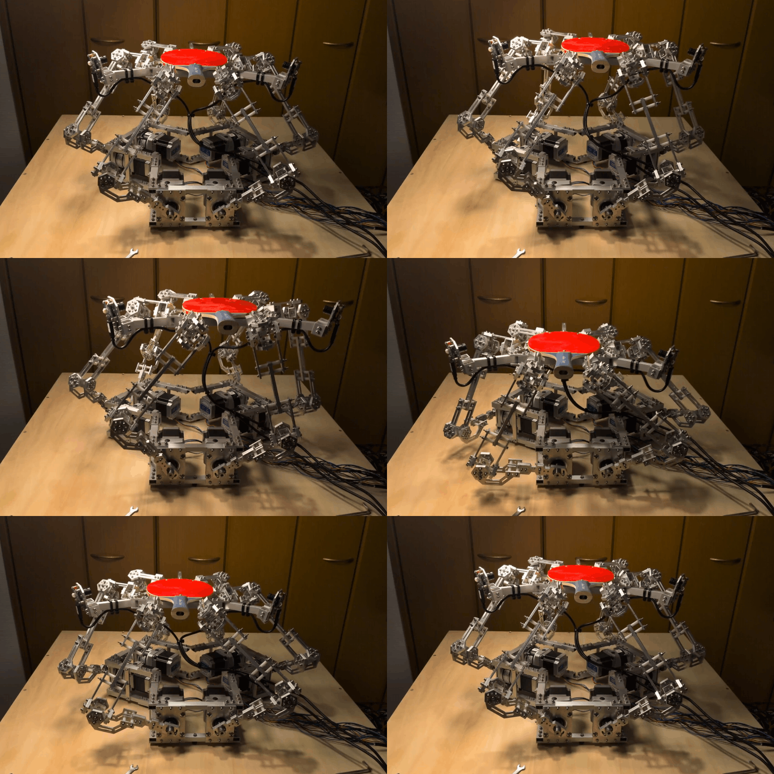
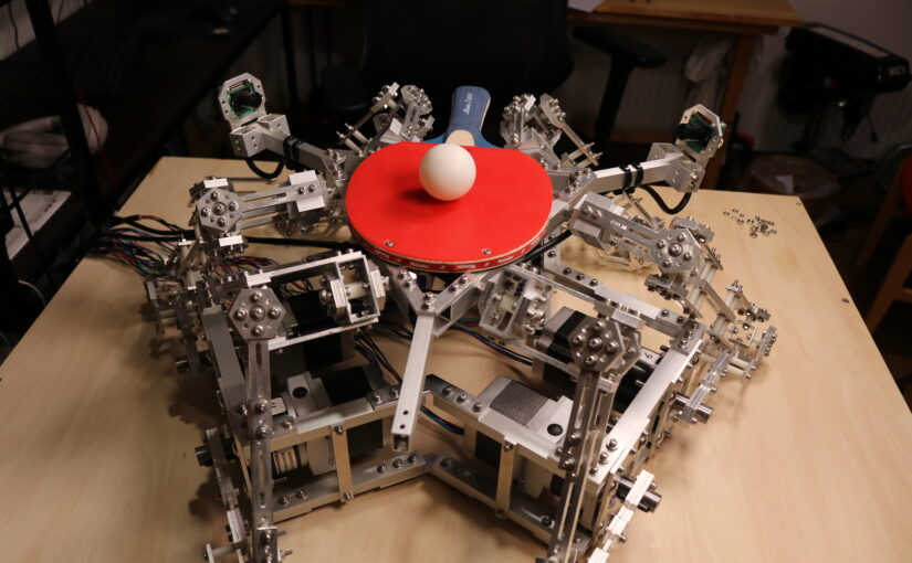
I made a machine I call the Hexa-Bouncer. It’s the newest addition to a line of useless but mildly interesting ball bouncing machines and the direct successor of the Octo-Bouncer.
Components
The Hexa-Bouncer requires the following things to work:
- 1x Teensy 4.0 Microcontroller running this code
- 6x StepperOnline CL57T stepper motor drivers
- 6x Nema 23 Stepper Motors with 10:1 planetary gearbox (link)
- 1x 36V 14A power supply
- 2x e-con Systems See3CAM_24CUG cameras
- 1x Windows Computer with GPU
- All the parts defined in the three Fusion360 projects here
- Six arms, one base, one triangle end-effector
- This custom Windows Application (made with Unity)
Mechanical Design
The Hexa-Bouncer is basically a rotary Hexapod with the minor twist that we use universal joints instead of ball joints on all six arms.
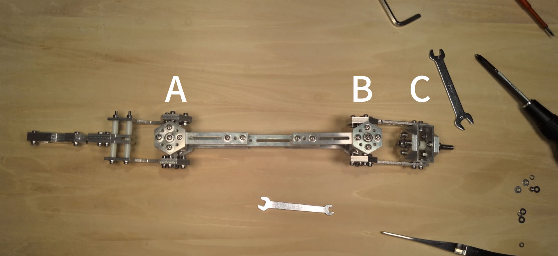
- A, B: universal joints
- C: wrist joint
Originally, I thought I could get the mechanical design to work by simply using two universal joints (A and B). However, after doing some IK simulation tests in Unity I noticed that the joint at position B needs to be able to rotate around the end-link’s axis (I talk a bit about this in the video at the top of this blog post). That’s why I had to add wrist joint C.
Having not only universal joints, but also wrist joints makes the thing look a bit clunky. Ideally we’d use a universal joint at A and then a ball joint at B and get rid of the now redundant wrist joint C. However, I simply couldn’t find solid and reasonably priced ball joints that would fit my design (where are y’all getting your ball joints?!), so I decided to stick to what I know works (designing my own joints with ball bearings) and call it a day.
So How Does It All Work?
The two cameras are sending image data to the PC (via USB bus) at 120 frames per second. We extract the 3D ball position from the two camera feeds (cameras are attached at an 120 degree angle to each other). So now we get a fresh 3D ball position every 8.33ms in our Unity Application. We use this data to predict when the ball will come down again and hit the paddle (to judge when the next upward motion should start) and how much the paddle needs to be tilted while moving upwards (a PID controller for X and Y axis).
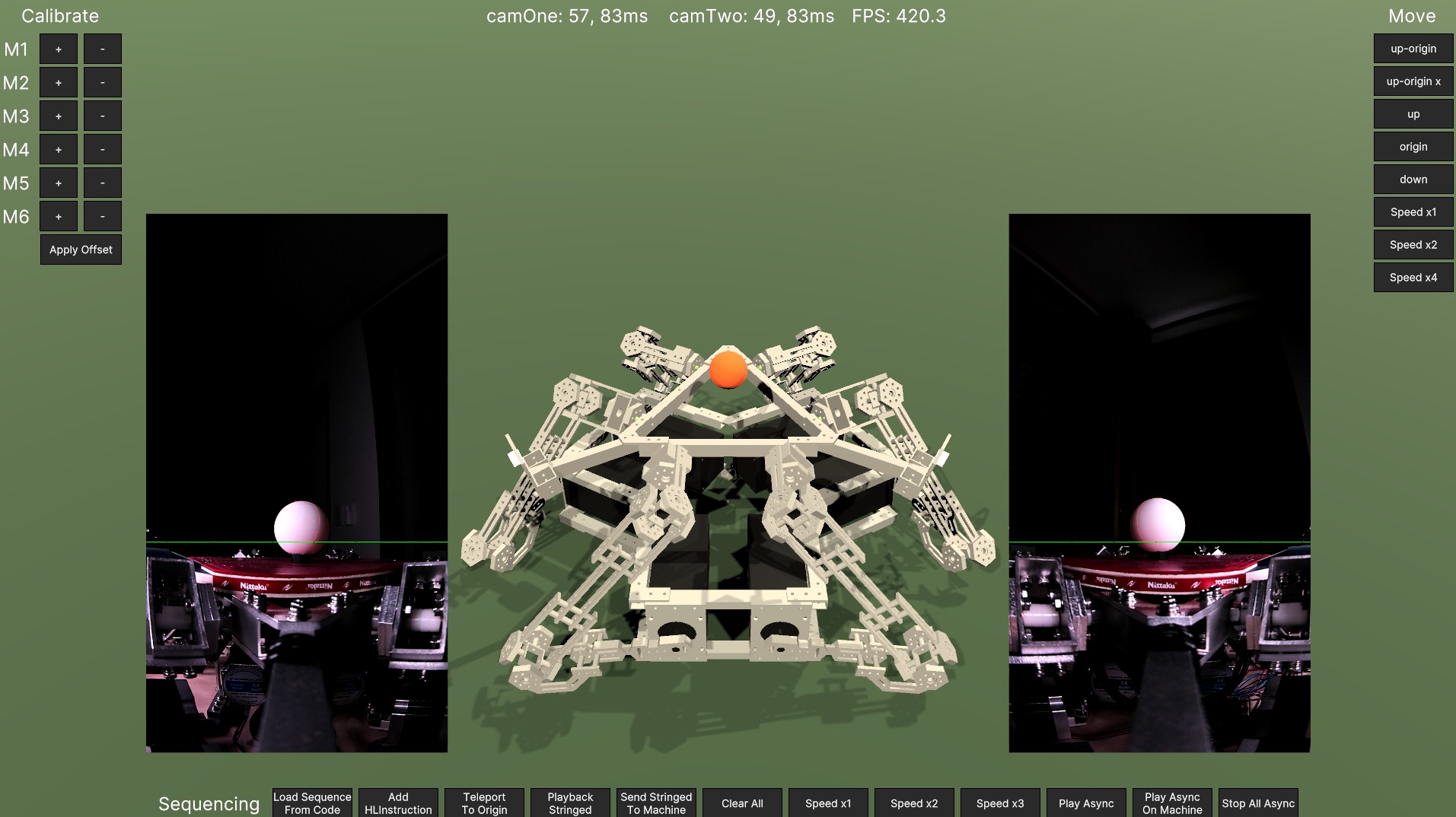
Above picture is a screenshot of the Unity Application (Github link) showing the virtual machine (digital twin) and both camera feeds.
Motor Pulse Generation
One thing I wanted to do with the Hexa-Bouncer is to make it not only move up/down and tilt, but also make it do more sophisticated moves, like the up-down-while-moving-in-a-circle move below.
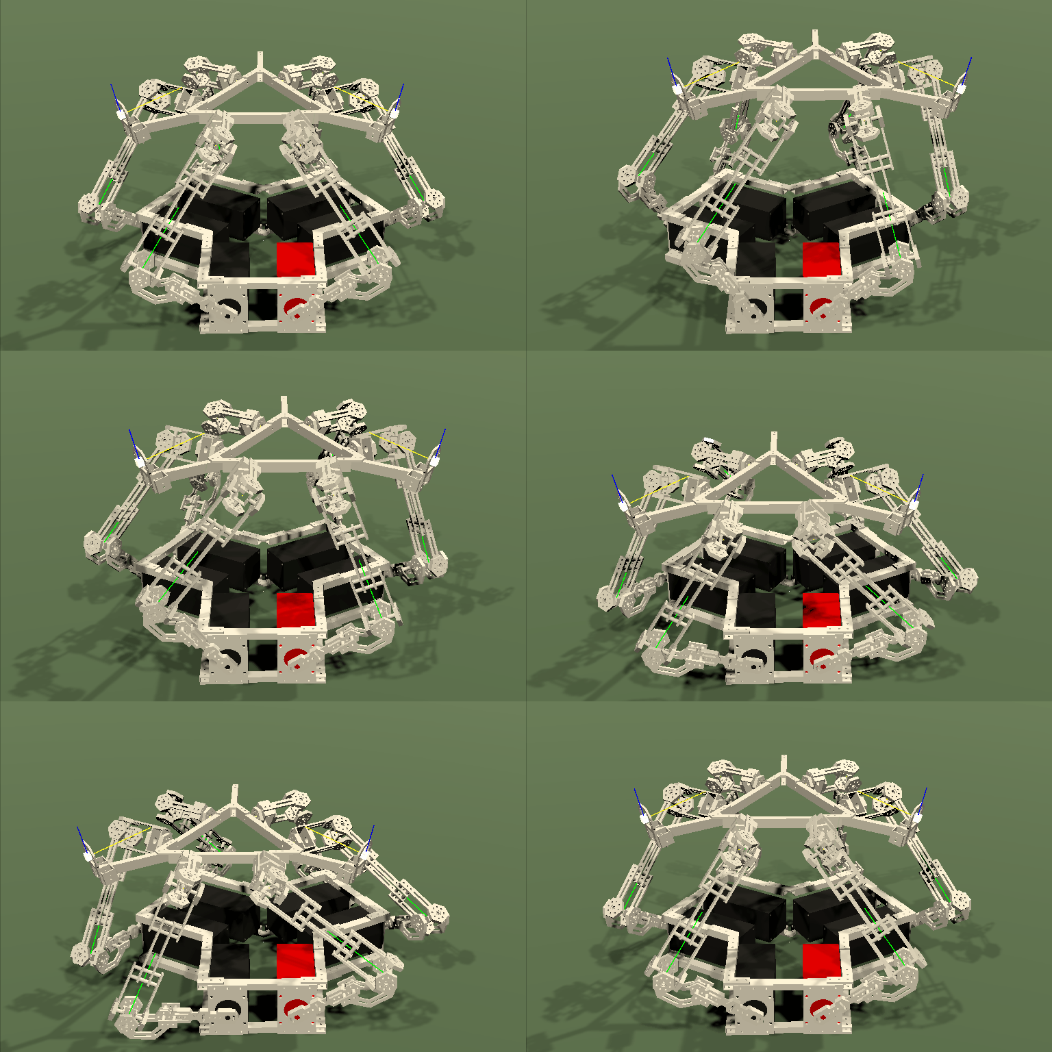
The difficult part about making motions like that possible was to design the pulse generation in such a way that complex motor profiles can be transformed into a fitting pulse stream.
For example, doing the motion above on the physical machine requires the red motor to follow a motor profile as shown below.
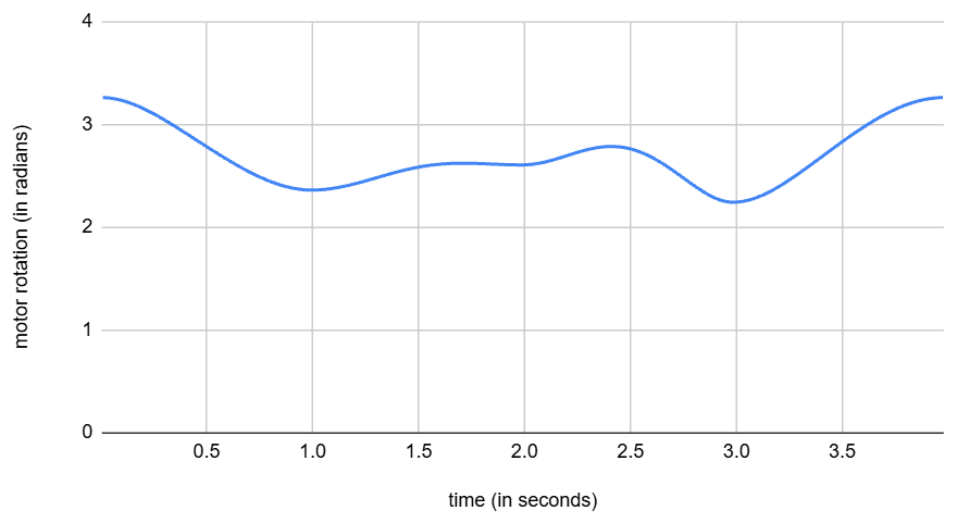
Generating stepper motor pulses for a pure sine wave is easy, but how do we generate pulses for a complicated curve like the one shown above? Some options that come to mind include:
- A: The microcontroller executes the same IK calculations as the Unity App in the pulse generation
- B: Fitting the curve to a function and passing the parameters needed to describe that function to the microcontroller. Microcontroller then advances the fitted function while generating pulses
- C: Sending a set of points on the curve and then let the microcontroller interpolate linearly between points on the curve
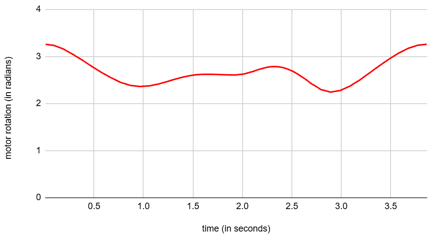
I implemented option C. A has the problem that our Teensy 4.0 simply isn’t fast enough to run the IK for all six arms every pulse generation interval. B maybe could’ve worked although I am again worried about the performance. C is perfect for our case since we can choose the points to be fairly close to each other and the result is thus smooth enough to not cause any problems at all. The only downside is that we need to send quite a lot of data to the microcontroller (all the data points for interpolation), but data throughput over the serial bus isn’t really a bottleneck in this project.
Here’s the resulting motor profile after implementing approach C with rough spacing between data points. Because we got quite a lot of space between the interpolation points we can see how the whole curve is just made up of multiple straight line segments.
Here’s what the motor profile looks like after making the data point spacing 5 times shorter.
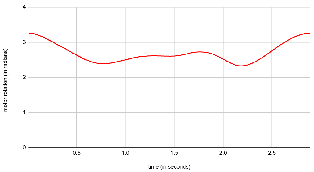
Now it looks almost the same as the original motor profile (the one we are trying to reproduce here). This more then sufficient for our project. Not at least because our mechanical structure isn’t perfectly rigid and there’s also the problem of backlash in the stepper motor gearboxes. So our machine can handle a tiny amount of deviation from the ideal motor motions just fine.
Below is the movement we get on the physical machine after implementing approach C. The movement is not quite as smooth as with the virtual machine, but I suspect that has more to do with how this particular mechanical design gets a bit unstable the further away the end effector gets from the center than with how the pulses are generated.