This entry is about a small stepper robot arm I made a while ago. In this post, I will first talk a bit about how I built it and what my thoughts were while doing so. After that, I will show some moving footage of what the thing is able to do.
A Small Stepper Robot Arm?
Yes. It uses stepper motors, it is small, and it is a robot arm. So here you go; A small stepper robot arm. Here’s a half-minute-video with some footage of the thing just sitting there.
How the project started
Some years ago I watched a YouTube video about a micro servo robot arm. It is quite a masterpiece in both video editing and electronics craftsmanship. Having seen this video, I tried for a while to do build a similar robot arm with the same servos. The problem with servos is, that it is very hard to get them to move slowly/smoothly. I tried an approach to re-implement the servo’s controller by getting rid of the microcontroller in the servo and just using the driver-IC and potentiometer output in combination with an Arduino Nano. I wasn’t able to get satisfactory results, and as so often, I started doing other things and forgot about this project.
Then I stumbled upon this extremely cheap gear-headed stepper motor which goes by the name “28BYJ-48”.
The 28BYJ-48 stepper motor
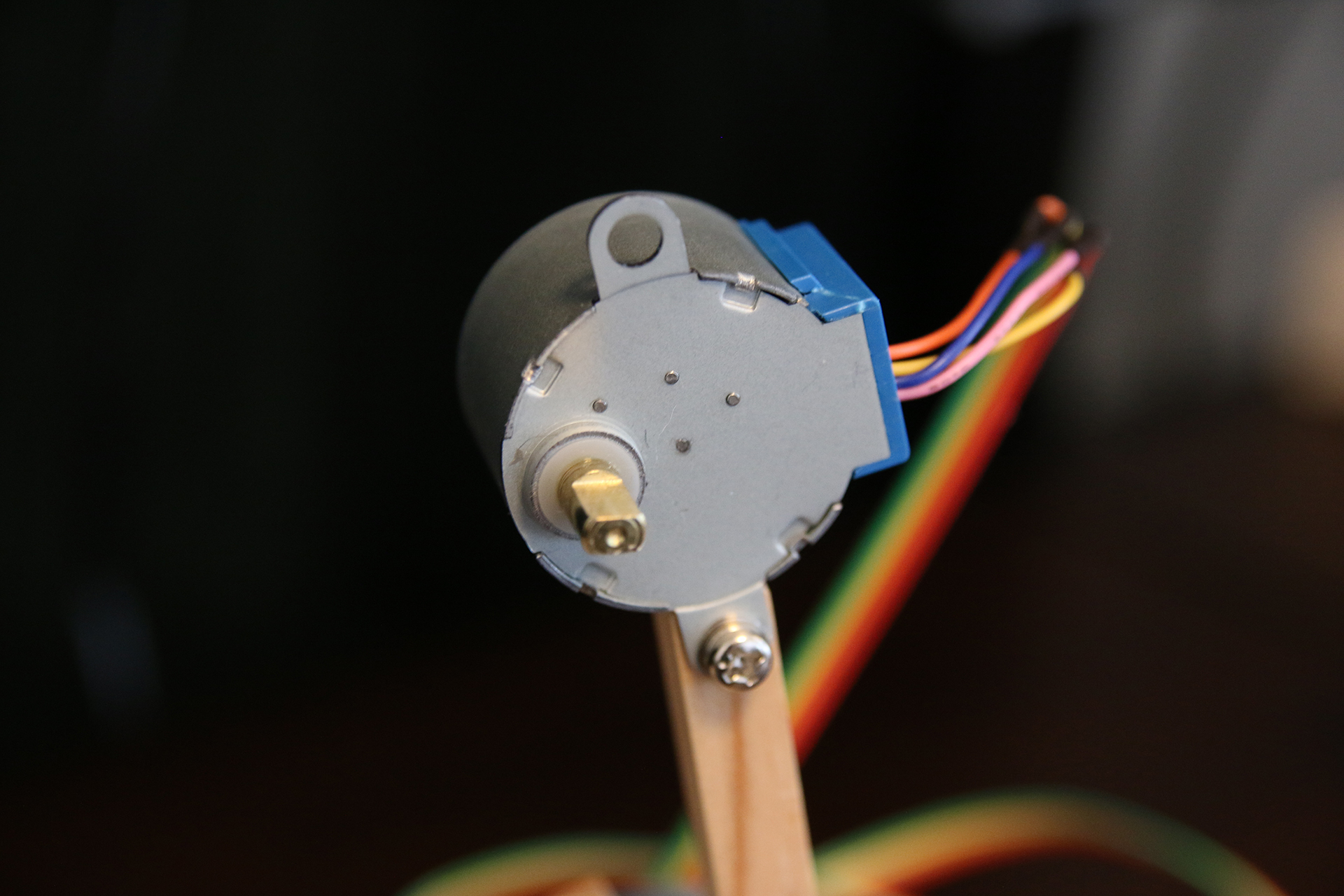
The fact that there’s a 1:64 gear built into housing is huge. It improves not only the precision (degrees/step getting smaller) but also increases the output torque. The only downside is the loss in speed (and maybe the mechanical play induced by the gear). But the speed loss isn’t even a downside since we don’t really care about it in this project. We want the robot arm to be moving in an elegant fashion. Speed isn’t important.
And here’s where the next hurdle came into view. Stepper motors are great because you can tell them how far to turn in “steps” (strictly speaking it’s the stepper’s driver-IC you tell how many steps to move). The problem now is to send steps in such a way that the stepper motor will be starting/stopping smoothly.
To accomplish this, I decided to use the grbl. Because grbl will produce an accelerating series of pulses for you. But – as so often when tinkering with stuff -yet another problem materialized. The grbl, as awesome as it is, doesn’t support more than 3-axis out of the box. I needed at least 4. Luckily, there’s a 4-axis fork of grbl here.
The next problem had to do with the stepper motor & stepper driver-IC combination. The A4988 stepper motor driver works really nicely with grbl. But the internal wiring of the 28BYJ-48 stepper motors isn’t compatible with the A4988. Luckily again, there’s something we can do about this.
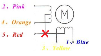
We need to cut the red wire! Just like shown in the illustration above. Here’s a very informative blog post about how exactly to achieve this.
After loading the grbl fork into the Arduino Mega and dealing with all the problems mentioned above, I finally got some movements out of the motors. I was using an open source software called “Universal-G-Code-Sender” to send some basic move-commands.
A great thing about grbl is, that it transforms your Arduino into this fully configurable stepper controlling unit. Parameters you want to change do not even need to be changed in code. Configuration can be done via serial (e.g. “COM1” or what have you). After connecting the Arduino to the computer, just open the “serial monitor” in the Arduino IDE (Ctrl+Shift+M) and send “$$” to the Arduino. The response will look like this.
$0=10
$1=255
$2=0
$3=0
$4=0
$5=0
$6=0
$10=1
$11=0.010
$12=0.002
$13=0
$20=0
$21=0
$22=0
$23=0
$24=25.000
$25=500.000
$26=250
$27=1.000
$30=1000
$31=0
$32=0
$100=250.000
$101=250.000
$102=250.000
$103=250.000
$110=1000.000
$111=1000.000
$112=1000.000
$113=1000.000
$120=50.000
$121=50.000
$122=50.000
$123=50.000
$130=200.000
$131=200.000
$132=200.000
$133=200.000
These are all parameters and a quick search for the grbl documentation will reveal their nature. I think I mainly lowered the value of the acceleration parameters $120 – $123 and set $1=255 to make it keep powering the motors even if they aren’t moving (because they need to hold the arm in place; Keep it from collapsing).
So at this stage, we got an Arduino controlling A4988 stepper motor driver-ICs which in turn are powering the stepper motors. And we are sending movement commands from a PC over serial to the Arduino. In the case, you are wondering how exactly the things are connected to each other just scroll down. There is a section where I talk about the schematics.
Building the mechanical arm
One thing we don’t have yet is the actual arm. We just got motors spinning. So let’s get that sorted out.
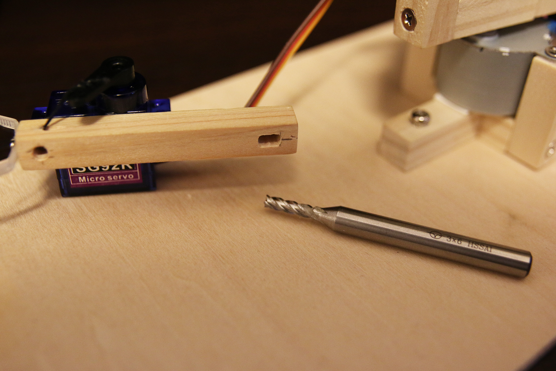
Building the arm turned out to be easier then I thought. Because of the shape of the motor shaft, milling a rectangular kind of hole with a 3mm cutter did the job.
Building the replica arm
Now we got a stepper robot arm. So far so good. We are able to move it by using a software like the “Universal-G-Code-Sender”. So far so good. But something seems wrong. It is hard to teach the arm how to move because all the movements need to be fed to the robot arm as position data. How can we make this interface better? A replica arm seems to be a good solution. Here’s some footage of moving the robot arm with the replica arm interface.
That’s the goal. And one way to achieve this goal is by using another microcontroller, connecting some potentiometers to it, and setting it up in such a way that it sends data about how far each potentiometer is rotated to the Arduino which is driving the stepper motors. Fair enough. However, for some strange reason, I decided that a Raspberry Pi 3 has to be used. Maybe I did it because it is generally faster to throw together some code in Python as supposed to C. I don’t know.
Here’s what I ended up doing: I got the Raspberry Pi 3, connected an MCP3006 A/D Converter to it (no analog input on the pi), and put some code in it. The code just reads all the analog inputs on the MCP3006 and formulates some move commands on the basis of said data. Then there’s the record & play functionality and some other minor stuff. Maybe that’s why I thought using the Raspberry Pi was better.
Here’s the complete Code for the Raspberry Pi 3:
github.com/T-Kuhn/StepperRobotArm
And while we’re at it, here’s a fork of the 4-Axis grbl code:
github.com/T-Kuhn/grbl-Mega-4axis
Building the Gripper
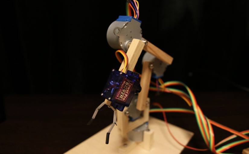
No robot arm without some kind of gripper. Some kind of thing which enables the arm to interact with its surroundings. Doesn’t have to be a gripper, but this time I went for a more classic gripper-like approach.
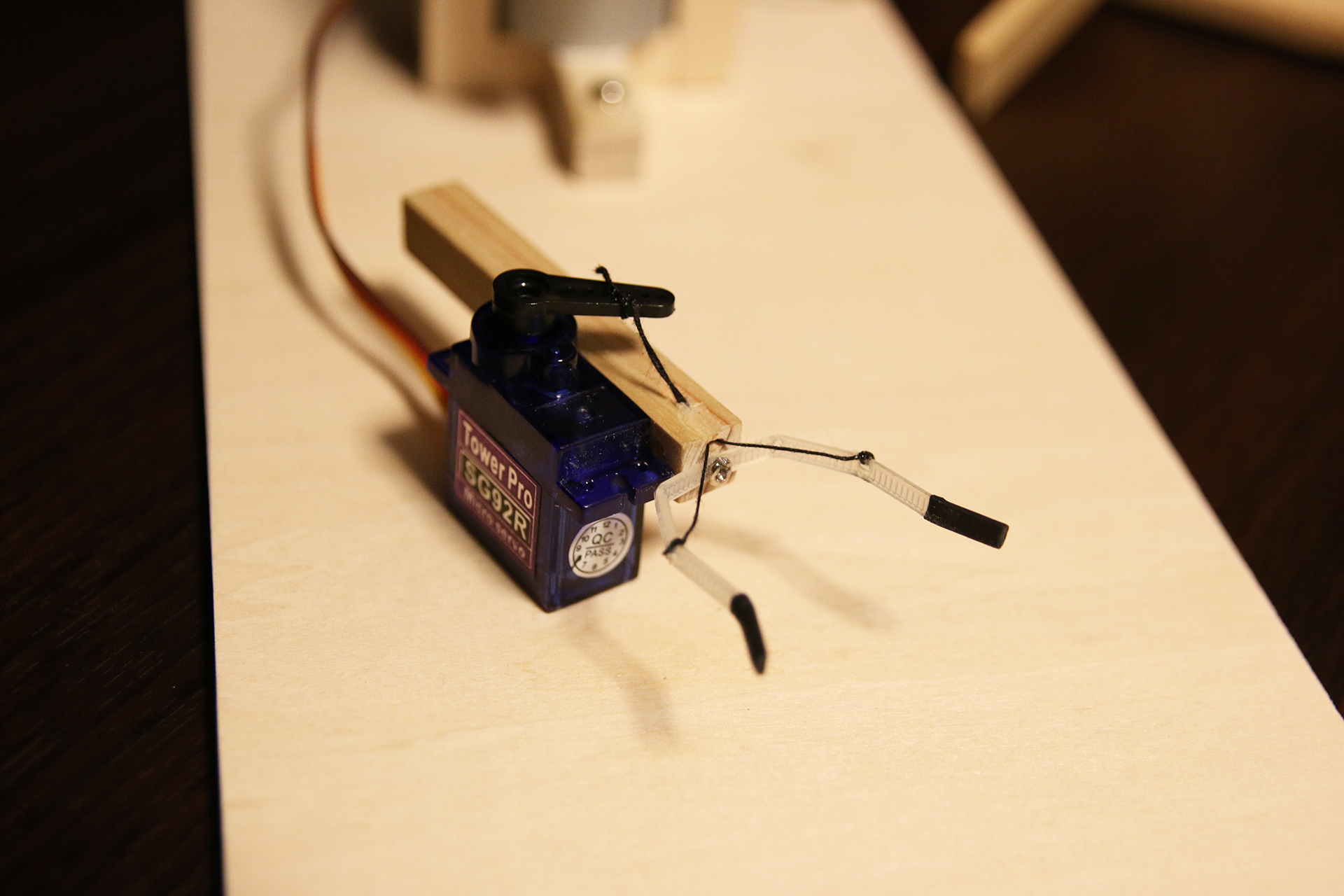
It is basically just a cable tie with some strings attached to it. Look at it closely and you will see. Now that we got a gripper, we can finally move stuff around. Here’s some footage of the robot arm doing exactly that.
How are the things connected?
Time to talk schematics. I finally got myself to draw a complete schematics of this small stepper robot arm project. There’s everything in it: The Arduino, The Raspberry Pi, the replica arm potentiometers, the A4899 drivers, etc. Click the image below to get the PDF.
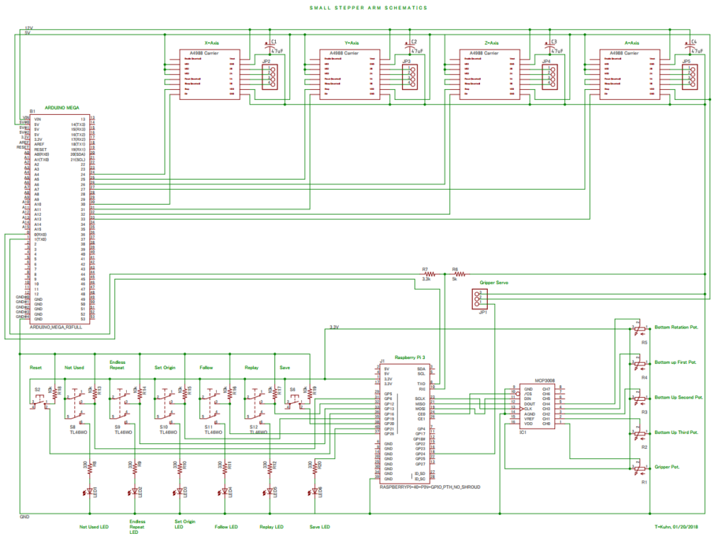
Some words about the schematics. You might notice that I set the stepper motor voltage to 12V even though the stepper motors are rated 5V. You might want to buy the 12V version of the 28BYJ-48 stepper motor. But then again, running the 5V version on 12V isn’t that big of a deal. Just be careful to set the current limiting to a very low value and you are good to go. This might depend on your version of the A4988 driver chip. It worked well for me.
Even though this post isn’t a tutorial per se, I tried to get enough information in it for anyone to get a similar kind of robot arm working. Leave me a comment if you got questions/suggestions.
Thanks, very informative presentation.
Really nice robot.
Thank you!
Nice work .Thank you ………I was looking for a way to run stepper from raspberry pi through arduino and grbl
Can I make this Robot arm using microcontroller 8051
If you want to use grbl to generate pulses for the steppers an Arduino is the best choice in my opinion!
Please i want to have a bit tutorial on this where is the code for arduino ?
1. Can we use arduino for reading the pot’s information ?
2. Can we use nema 17 stepper motor with A4988 Driver board ?
3. Motors connected with A4988 driver and arduino as output MODULE and arduino connected to pots as an input MODULE and the mediator between INUPUT AND OUTPUT MODULE will be Raspberry pi with buttons (play,record,loop….etc)
Can you please help me with this ?
use this link for the code of arduino
https://www.youtube.com/watch?v=bLnAJ-mSElE&feature=youtu.be
Thank You 🙂
please sir can you please send me the code
Hi thanks for this great guide! What rating should the potentiometers be? I’m new to electronics so I need everything spelled out lol. Can I use an orange pi or Arduino instead of a raspberry pi?
Sir.
Do you have the final code for this inspiring and fabulous project on robot arm.
Regards, UZAIR.
Hello!
I am trying to make a scara robot to work with grbl. Could you please give me some tip about how to configure the inverse kinematics in the grbl code? I am also trying to use 28bjy-48 step motors.
Thanks very much!