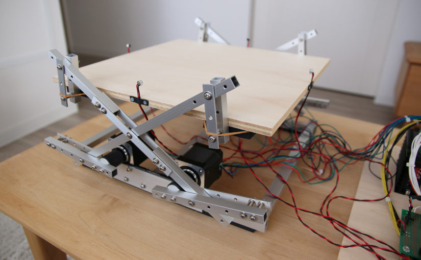
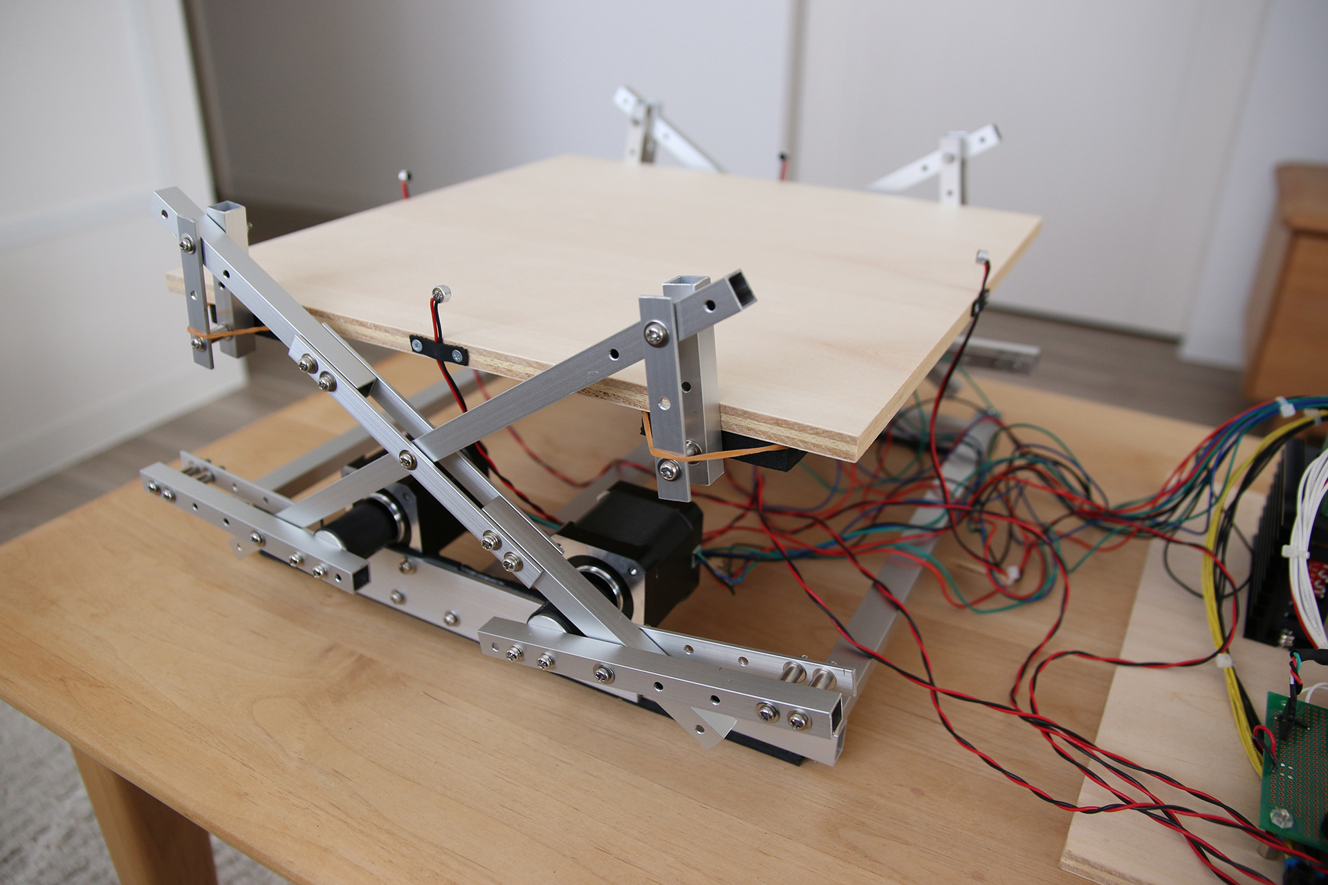
This is a PID controlled ball on a plate machine with the sole goal of keeping the ping pong ball bouncing for as long as possible. I have been trying to build ball bouncing machines for a while now. This is the newest iteration!
How does it work?
The location of the ball is calculated from the time difference when the ball’s noise is hitting the mics. This time difference is calculated for each mic pair separately (one pair for each axis on the 2-dimensional plate). The noise from the ball hitting the plate is a very loud one; It was surprisingly easy to distinguish it from other sounds. You can talk casually nearby the machine and it won’t be affected.
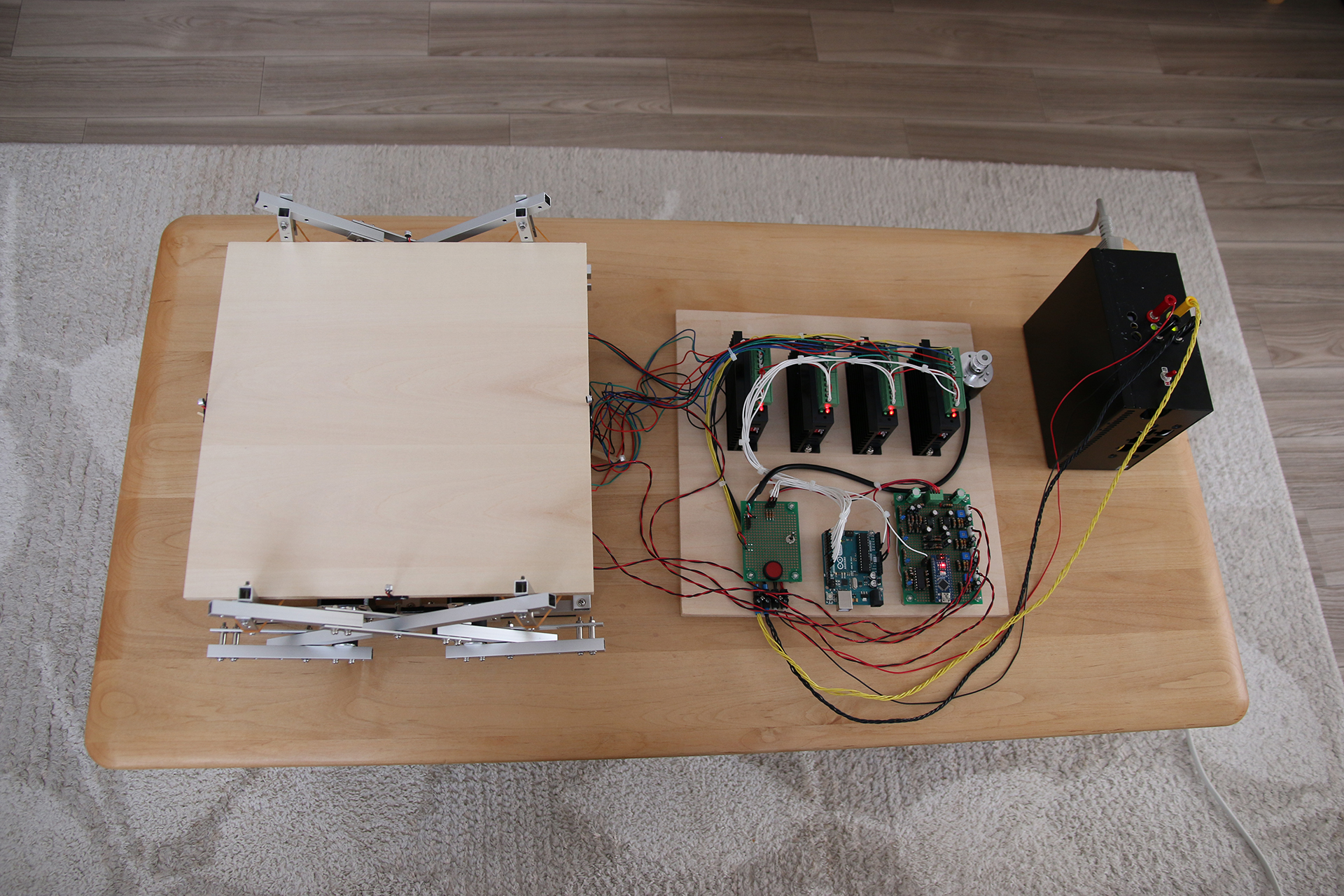
There is a small analogue circuit to process the signals from the mics. Each mic sets a flip-flop (a thing to store either a “1” or a “0”, digitally speaking) if it’s amplitude surpasses an adjustable voltage level. An Arduino Nano is watching all the flip-flops and resets them after they all got set (the blue LEDs in the video show the current flip-flop states). The Arduino checks the states as fast as possible, this allows for a reasonable accuracy. As soon as, for instance, the left mic on the x-Axis registers a load noise and sets the flip-flop the Arduino will start counting the cycles (literally cycles of a the mic-check-loop in code) until the opposing mic registers the load noise as well. After both of the mics registered a sound, the cycle count might be at 183 (the range goes from -200 to 200. 0 is when both mics register the noise simultaneously). This is used as position data. The same cycle counting is going on for the other mic pair, thus we are able to extract 2-dimensional data about where on the plate the ball hit.
The gathered position data is then sent to another Arduino (via serial) that uses this data to tilt the plate in such a way that the ball will – hopefully – not fall down. The plate tilting business is done by using the results of 2 separate PID controllers. One for each axis.
The PID Controller
I am using these three things to control the tilt on each axis (the plates x- and y-axis):
- How far away is the ball from the center? Correct in such a way that the ball will go towards the center proportional to the distance measured from the center.
- Where is the ball moving? Correct in such a way, that the movement can be stopped. The amount of correction is proportional to the measured distance the ball was moving in the last 2 data points.
- Does the ball show a tendency to stay in a certain spot on the table? Add a little correction proportional to the distance from the center to get rid of such tendencies (this should get the table centered over time). And this value will compound over time.
Those 3 things essentially are all the parts of a PID controller (the P-part, the I-part and the D-part). All of these 3 things are done for the x-axis and the y-axes separately. The PID code is in here.
One of the struggles with the PID is that I am not able to apply the calculated correction tilt the same time the ball hits the plate. Because when the ball hits the plate I finally know where it is NOW, and in which direction it is moving. So this data has to be used on the next bounce. Applying the correction is 1 bounce delayed. I think I could get better results if it wasn’t for this delay. But with this setup the delay is inevitable.
Another problem, of course, is that the data is so scarce. The ball might move in 3 bounces from one end of the table to the other. Considering that the tilt correction is delayed by 1 bounce there are only 2 bounces to get the ball to stop.
The ball might also gain a bit of spin. This is also hard to handle.
Air moves in every which way. That ping pong ball is moving through the air above a 30cm/30cm plate which is moving up and down constantly! Even in a room without any wind, the table alone creates quite some air flows.
The Pulse Generation
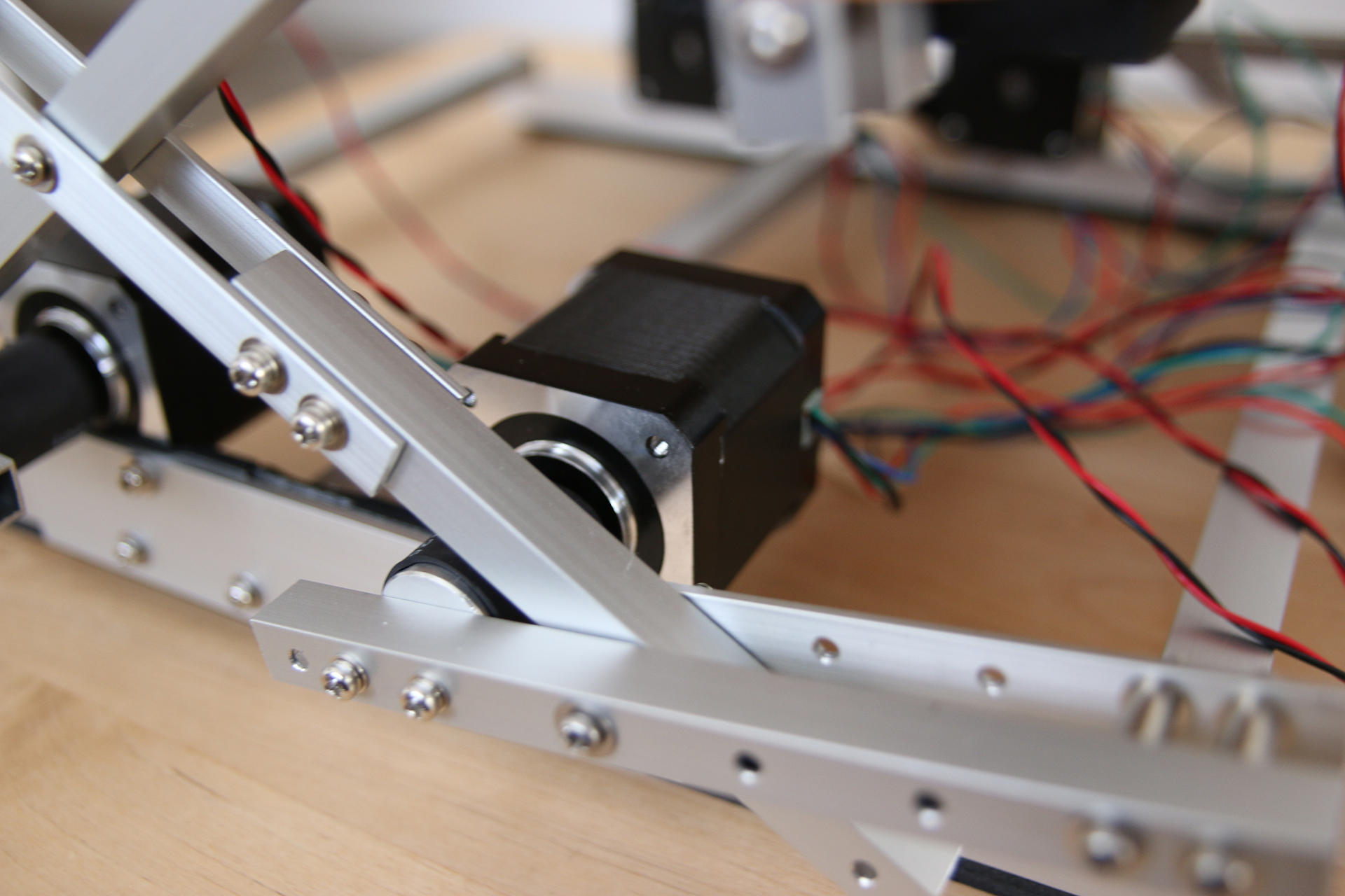
It’s worth mentioning that I didn’t use a library to generate the pulses for the stepper drivers. I programmed an algorithm to produce pulses which result in a sin-like acceleration followed by an immediate sin-like deacceleration of the stepper. There are many great Arduino stepper libraries out there. The only problem was that the ones I found all accelerate linearly and take their sweet time whenever a change in direction occurs. Time is precious. This machine has to go up, stop, and almost instantly start going down again. It makes sense to use a linear acceleration for CNC applications of course, but this PID controlled ball on plate machine needed a smoother, faster pulse-generating-algorithm.
Code
Here’s the Github repo with all the code for this project:
github.com/T-Kuhn/Stepper-Juggler
Fotos

Did you like this PID controlled Bouncing Ball on Plate machine? Click here for more.
This is cool. The last comment I left got kicked back as a “suspicious bot”.
Hi Alex,
Thanks and sorry about that. Will keep an eye on the issue with the comment checking mechanism!
Ok so, you might be able to use this device to match ping pong balls. I don’t think they exist yet. For example, run 500 balls on this device and compare plots. Take 5 balls that have very similar bounce patterns. A package of 5 ping pong balls could be sold as “matched”. The claim is that matched balls reduce the ball’s impact as a variable in a ping pong match.
That sure is an interesting thought. But I first had to eliminate all the other factors which might contribute to the balls unpredictable movement. I am thinking about the surface of the wooden plate being not 100% flat. And also the fact that it is wood isn’t ideal when thinking about testing ping pong balls.
But then again, all balls would get tested on the same machine. So a well-balanced ball should do better on the average.
Thanks for sharing that thought!
Great project. I think detecting the position of the ball with mics is a simple and clever concept. Was it your idea?
Hey Alperen,
Thanks. It was my idea to use an acoustic location determination approach for this kinda machine. I first thought about a machine catching a ball which is bouncing towards it. But I somehow got carried away.
This is so great. Congratulations. Can I ask about the build: are those pre-machined aluminum parts, or did you cut/drill them from blank stock? It’s a polished look.
Hi JWebb,
The aluminium parts are all made from differently shaped aluminium-profiles which I bought at the DIY-store down the street. Cutting and drilling was done by me. I mostly worked on it on the Weekends. Took around a day each to get those scissor type lifter things done.
tkuhn,
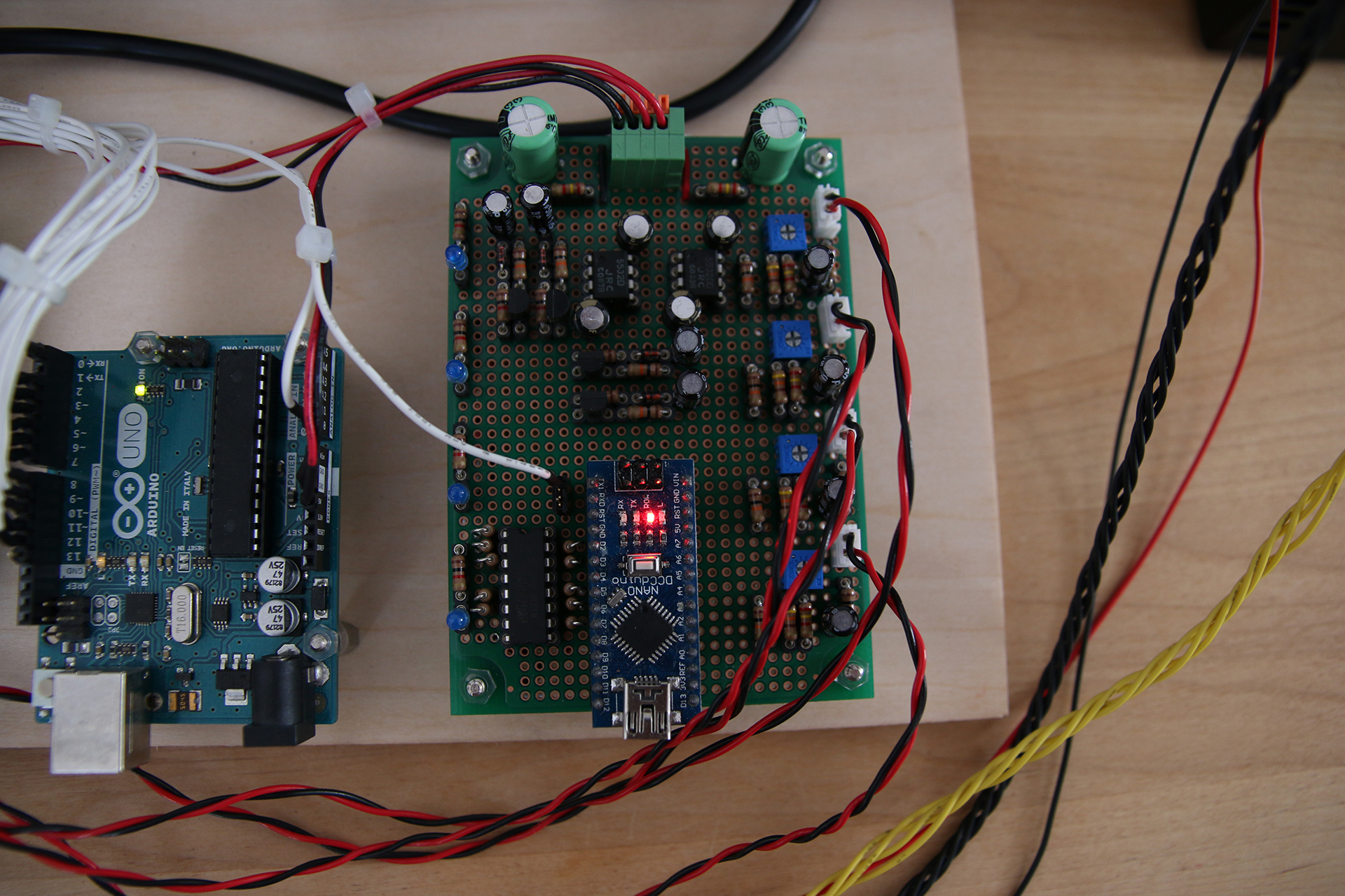
I love the idea of the project and decided to build a similar model for my semester project. I am currently trying to figure out the component layout on your board but having a little trouble doing so. If possible, is there a way that you could post the underside of the board or even better a schematic of the circuit? I can see most of the resistor values and figure out the capacitors myself, along with the 555s, but what chip is being used on the side of the NANO? Thanks for your help in advance!
Hi ChipEECE,
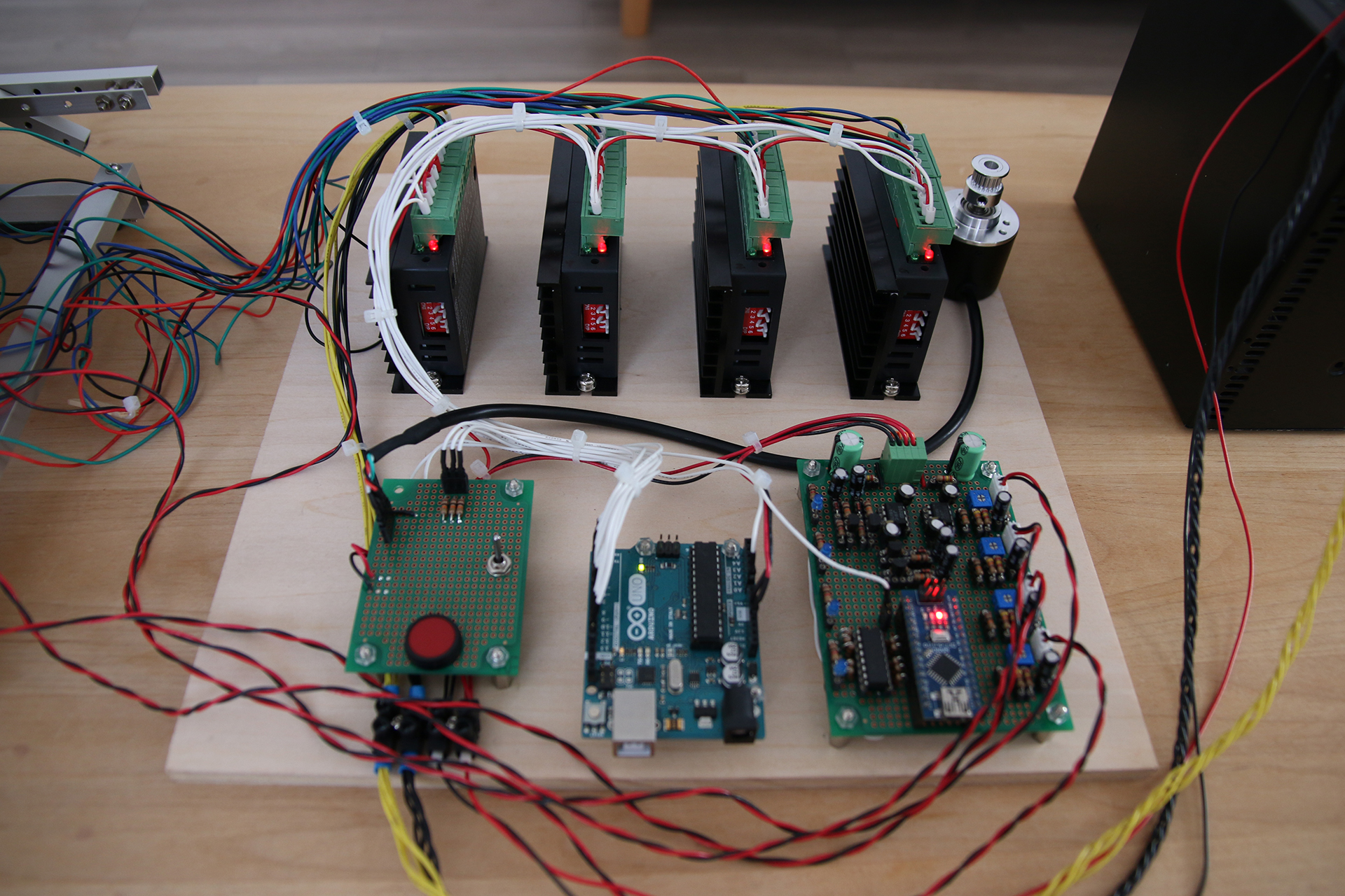
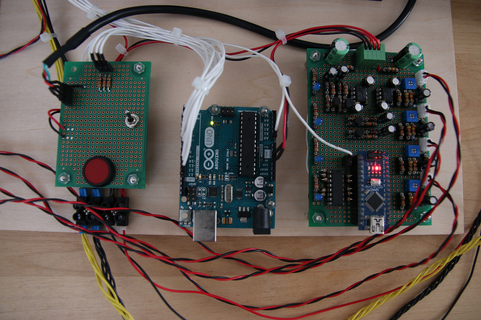
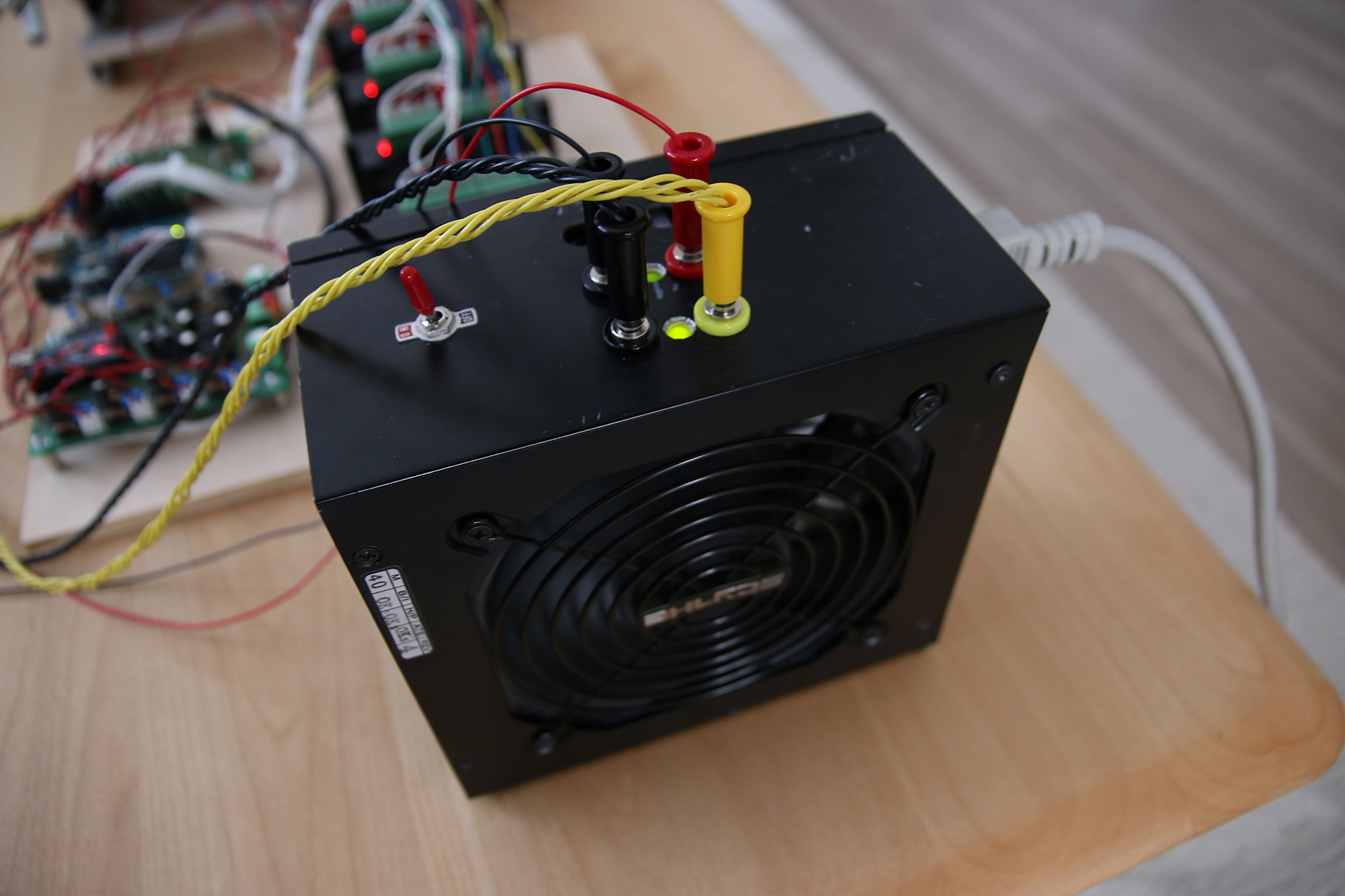
The Board with the Arduino Nano contains the following:
– 2x Op Amp NE553 (the smaller 8pin ICs)
– 1x TC74HC279AP S-R Latch (the IC on the side of the Nano)
The Op Amps are to amplify the 4 mic signals. The S-L Latch is used to store a single bit value which indicates that the corresponding mic surpassed a certain threshold (loud noise was registered. Ball has probably hit the plate!)
I think there’s a pic of the bottom side of the board here:
http://www.electrondust.com/2018/08/13/afterthoughts-on-arduino-bouncing-ball-on-plate-machine/
Like it… well done
it would be awesome to have the schematics of your analog board as well as the details on the PID , stepper motors and controllers..
thanks
Hey PR,
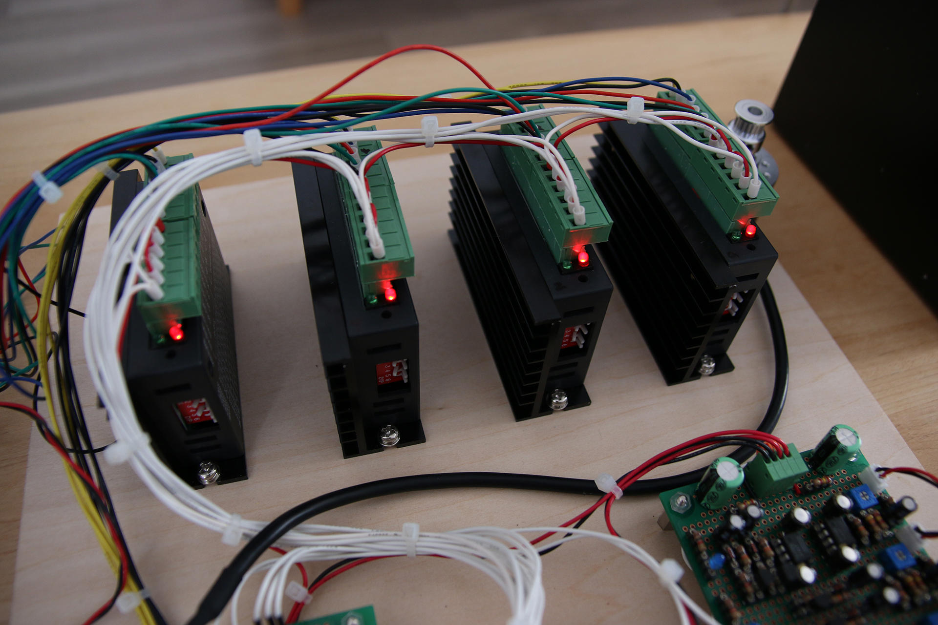
There are no schematics, sorry. The Op Amps are used in a non-inverting amplifier setup. Stepper motors used are Quimat Nema17 rated for 2A. The drivers are Quimat 4As. The PID implementation can be found in the code:
https://github.com/T-Kuhn/Stepper-Juggler/blob/master/CalculatedMoves/CalculatedMoves.ino
You definitely need a more advanced control method than just PID for this system, with some model based control you could predict where the ball is going to land next based on your past inputs and perturbations so you can correct based on that. I was also wondering how you currently determine when you need to move up, just based on time? Anyway, cool project.
Hi Casper,
Yes. It’s just time. You might wonder why it never gets out of phase. It’s because of the way the plate accelerates – reaches peak velocity – decelerates. The system is self-regulating and thus never getting out of phase because the time is set up in such a way that whenever the ball hits the plate too early it will hit a faster moving plate compared to when it’d hit on time. On the other hand, whenever the ball hits the plate too late, it’ll hit a plate which is already deaccelerating, so there’s less kinetic energy transferred to the ball and it’ll hit earlier next time.
You might be right. But did you take the one-bounce-delay problem into consideration when thinking about the control mechanism (I wrote about it in the blog post)? I think this is the main reason why the PID isn’t getting the ball centred and I am wondering what control mechanisms would handle this delay problem best.
The PID controller is doing next-bounce-position prediction using the current ball velocity across the plate in the calculation for the D-component. There might be room for improvement, but the main problem for the ball not getting into a centred position stems from the huge one-bounce-delay problem.
Hey Tobias,
Basicly you would predict where the ball will land next using the past locations and use that as input for your PID controller to correct with. Lets the ball just bounced on position XY0, then you want to predict the future position where it will land called XY1. You first look at horizontal velocity at XY0 by looking at the position before that XY-1, the velocity at XY0 is then the difference between those two devided by the time it took. Then after you know the velocity at XY0 you can predict where the ball will land next by looking at the angle and speed (which you can determine by looking at when the platform hit the ball) the platform hit the ball. Which some basic physics you can determine how the hit changed the velocity of the ball and where is will land. You will probibly need to add a small factor for air resistance somewhere to get a accurate prediction. To the test the predictions you could do another one of those visualisations from above to determine the error of the prediction.
Do you think it would be possible to calculate where a dart lands on a dart board with a 3-4 mic setup similar to this? I see in your latest revision you use opencv and image/video recognition but that would be in the way for tracking darts.
Would love to hear what you think about it before ordering parts and trying to build it myself.
Cheers! Thanks very much for the time you put into documenting your projects. It’s very inspiring and helpful.
HI T-Kuhn,
I just want to ask what is it the 4 black cards in the project?
And if you have a list of component it will be great!
Thanks
Hello
Are you new to SEO and want to rank #1 on google this upcoming year?
Here are 3 SEO strategies that will boost your rankings!
#1: Focus on content
#2: Optimize your title tag and your meta description
#3: Use Google Search Console
Subscribe here to learn more of my
Secret SEO Tips & Trics https://zeep.ly/WkJgE?=920
Thanks,
Mahalia Ranford
Please do not reply directly to this email!
Hello, I am studying at Düzce University. We would like to implement the project you have made. Do you have a chance to send a detailed list of materials?